Diffrence Between Industrial Design and Mechanical Engineering

Difference between Industrial Design and Mechanical Engineering

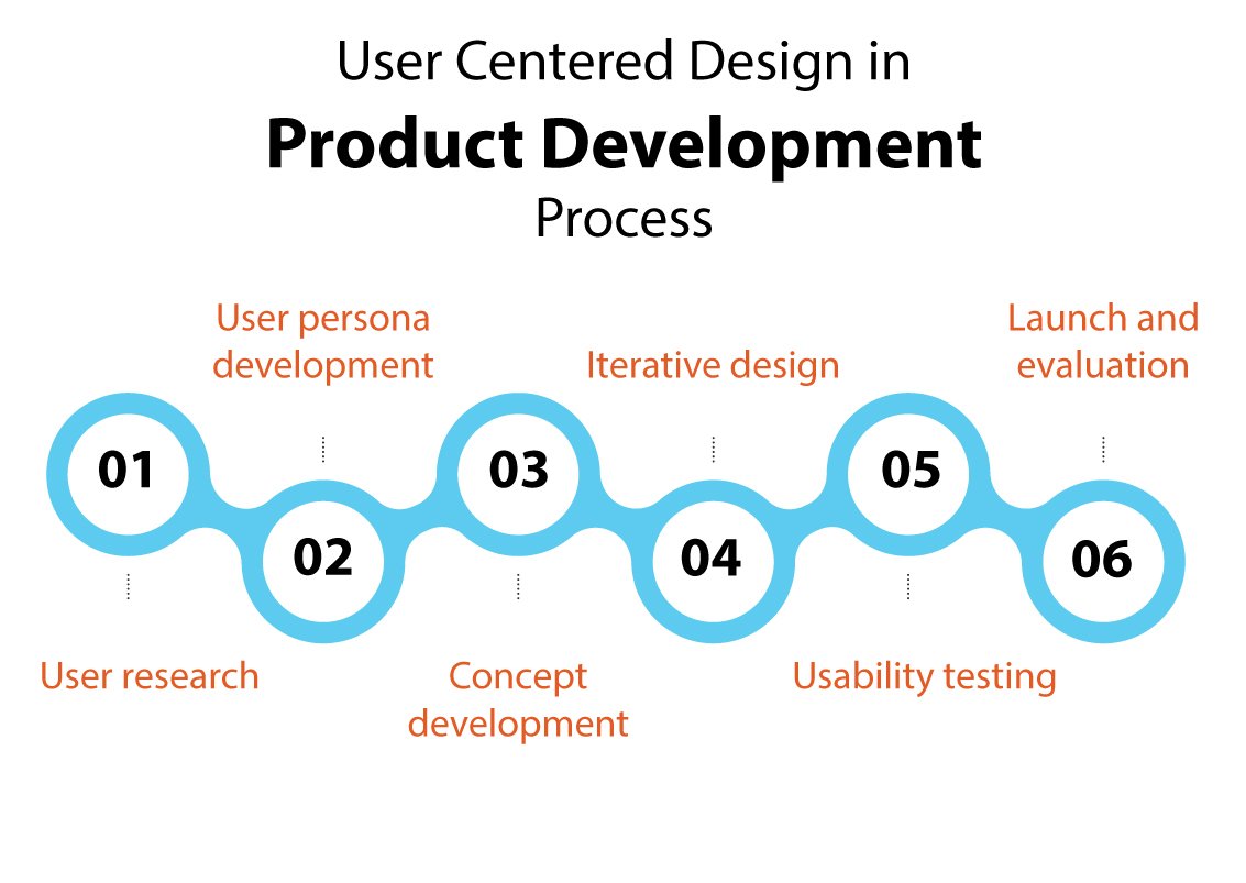
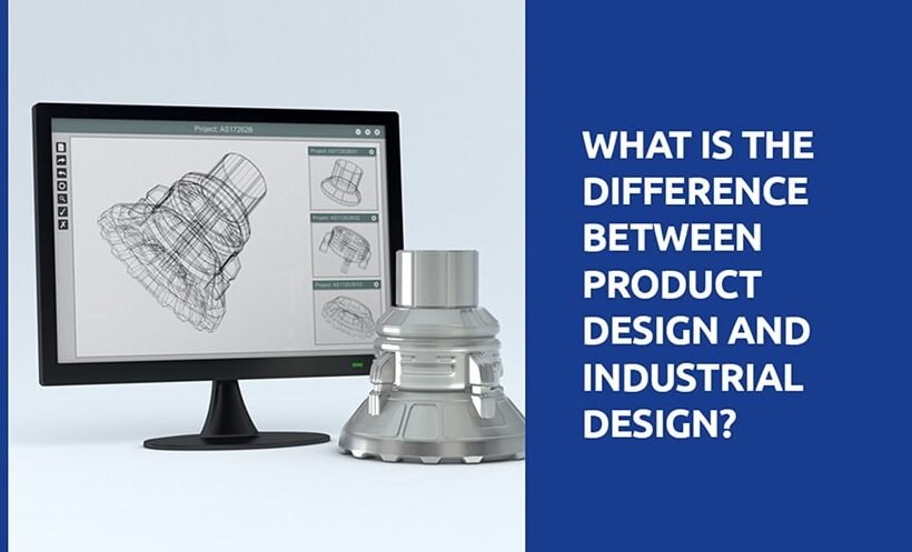
In the complex world of product development, where innovation is the driving force, two dynamic disciplines, Industrial Design and Mechanical Engineering, play pivotal roles. These two fields, seemingly distinct, come together to shape the products we interact with every day. In this comprehensive exploration, we will delve into the differences between Industrial Design and Mechanical Engineering, supported by real-world examples. Moreover, we will introduce you to Monarch Innovation, your trusted partner in achieving the perfect balance between aesthetics and functionality.

Industrial Design: Where Art and Utility Converge

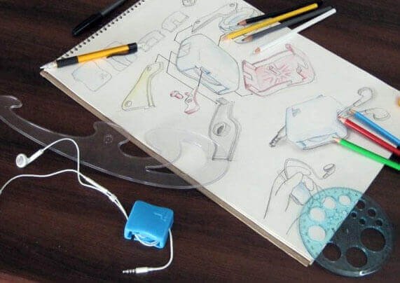
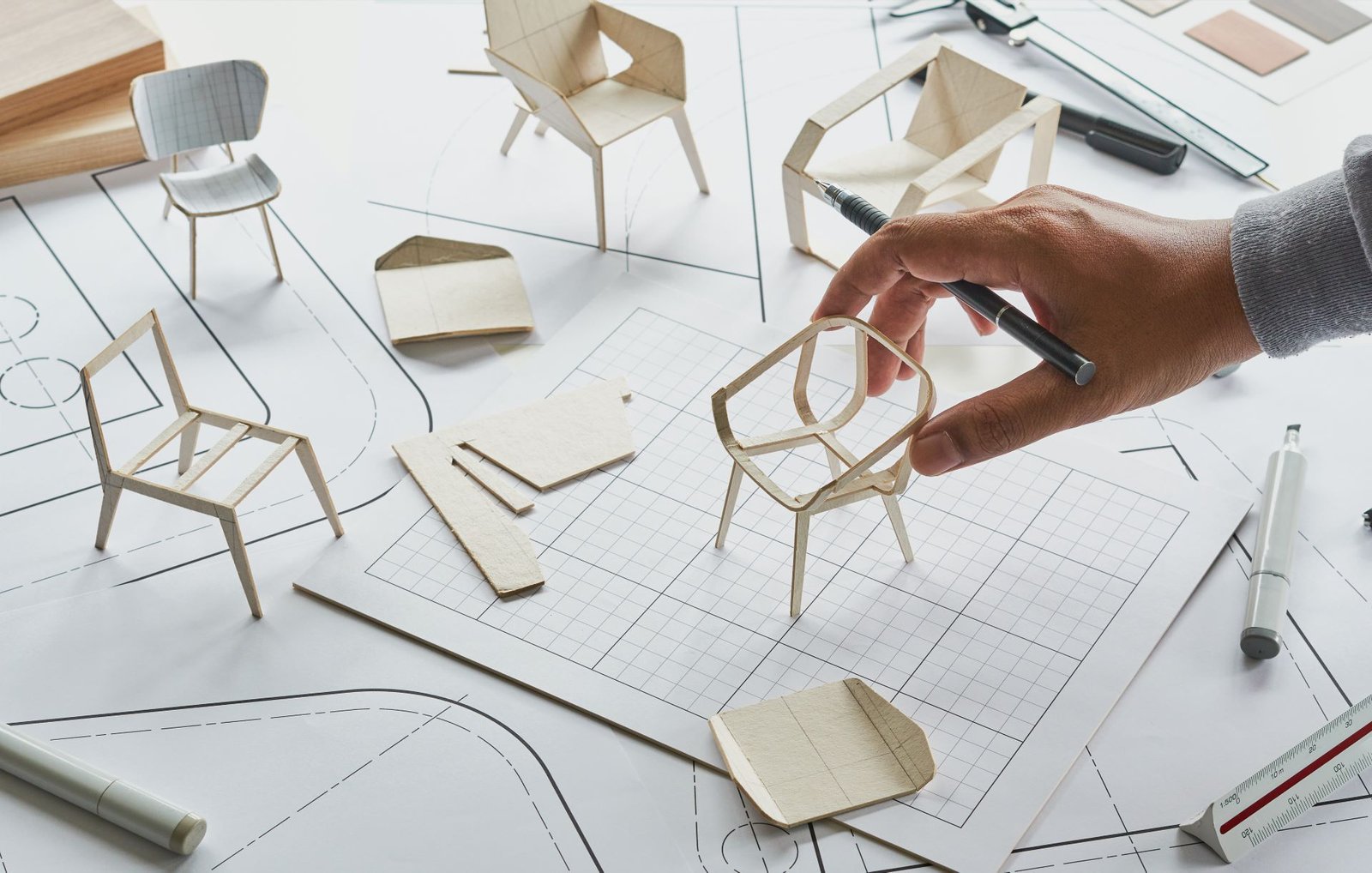
Industrial design is the creative heart of product development, blending aesthetics and functionality. Drawing from principles of ergonomics and unbounded creativity, industrial designers craft products that are not just practical but also visually captivating. They often follow an outside-in approach, prioritizing user experience and aesthetics.

Example: Think of the iPhone—a marvel of industrial design. Its sleek, user-friendly design and seamless integration of technology epitomize user-centric principles. Apple’s unwavering commitment to design has made its products iconic.

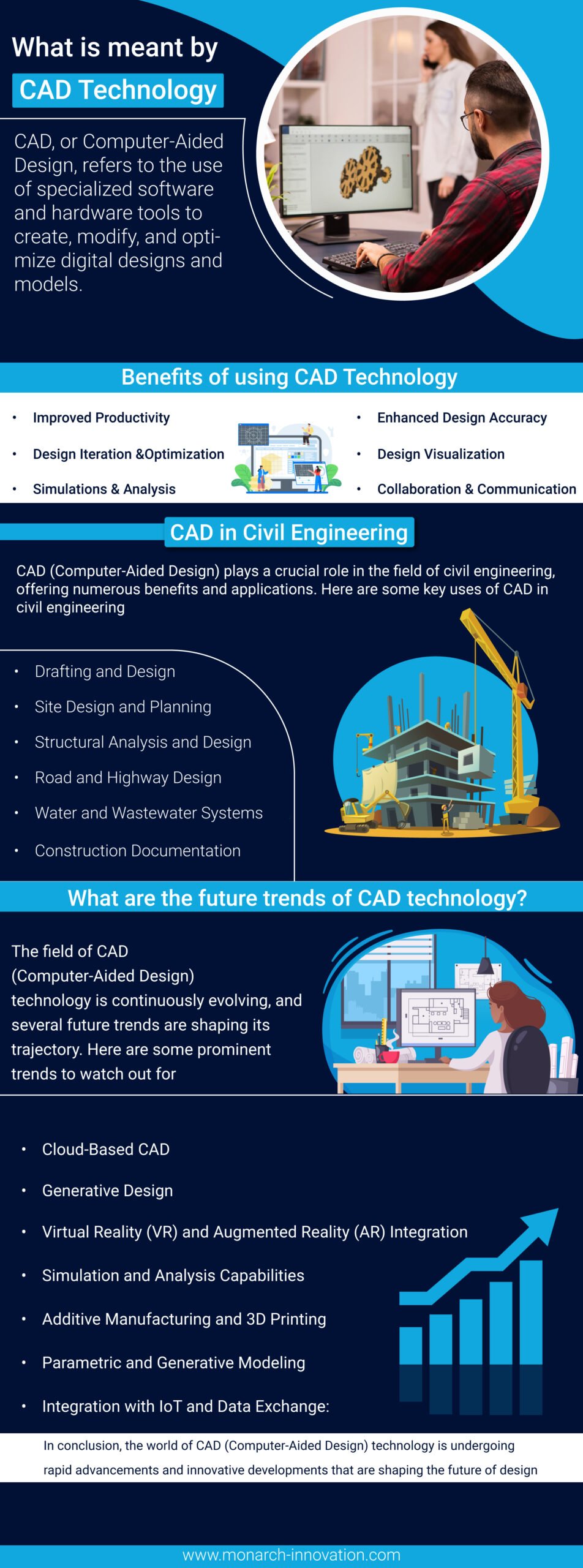
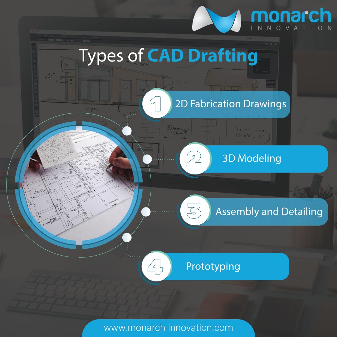
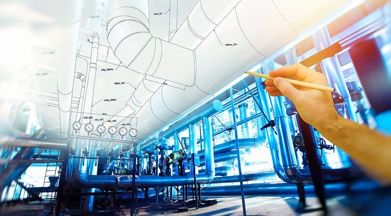
Computer-Aided Design (CAD): Precision in the Digital Realm

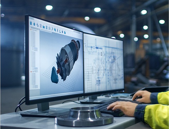
CAD (Computer-Aided Design) serves as the digital realm where engineers and designers transform abstract concepts into precise, three-dimensional models. This versatile tool is akin to a craftsperson’s toolkit, used to give life to intricate ideas.

Example: The Burj Khalifa, the world’s tallest skyscraper, heavily relied on CAD technology. It allowed engineers and architects to meticulously plan and execute the complex geometries and structural elements of the building.

Mechanical Engineering: The Science of Functionality and Reliability

Mechanical engineering forms the backbone of functionality and reliability. Rooted in scientific principles, mechanical engineers comprehend how objects respond to various forces and conditions. In the realm of product design, they take an inside-out approach, prioritizing performance, reliability, and manufacturability.

Example: The Boeing 787 Dreamliner showcases the prowess of mechanical engineering. Advanced materials, aerodynamic design, and innovative systems ensure fuel efficiency, reliability, and passenger comfort.

Choosing the Right Path: Project-Driven Decision

In today’s multifaceted landscape, industrial design firms may encompass mechanical expertise, while mechanical engineering company may house design-savvy professionals. CAD administrators often serve as versatile bridge builders, wielding the technical acumen needed to transform abstract ideas into tangible reality.

Example: When designing a high-end sports car, aesthetic appeal reigns supreme. Manufacturers like Ferrari engage industrial designers to craft visually stunning vehicles. However, beneath the surface, mechanical engineers ensure the car’s engine, suspension, and other components deliver top-tier performance and safety.

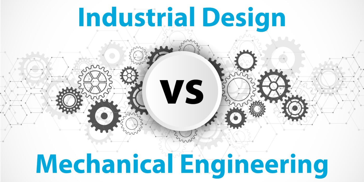
Pros and Cons: Industrial Design vs. Mechanical Engineering

Industrial Design:

Pros:

  • Aesthetic Excellence: Industrial design prioritizes aesthetics, resulting in visually captivating and user-friendly products.
  • Innovation: Industrial designers push creative boundaries, leading to groundbreaking concepts that capture attention.
  • Market Differentiation: Well-executed industrial design sets products apart, fostering brand loyalty and market success.

Cons:

  • Risk of Impracticality: Pursuing aesthetics and innovation may lead to challenging manufacturing processes and increased production costs.
  • Limited Focus: Industrial design may prioritize form over function, potentially overlooking critical engineering considerations.
  • Subjectivity: Aesthetic preferences vary widely, making it challenging to create universally appealing designs.

Mechanical Engineering:

Pros:

  • Functional Excellence: Mechanical engineering ensures products perform reliably and efficiently under various conditions.
  • Reliability: Rigorous testing and analysis lead to product durability, reducing failures and recalls.
  • Manufacturability: Mechanical engineers consider ease of manufacturing, leading to cost-effective production processes.

Cons:

  • Aesthetic Sacrifice: Mechanical engineering may prioritize function over form, potentially resulting in aesthetically lacking products.
  • Less Innovation in Form: A strong focus on functionality may stifle creativity in product aesthetics, leading to a lack of differentiation.
  • Complexity: Meticulous engineering can lead to longer design and development timelines.

Conclusion: Achieving the perfect balance

The distinctions between industrial design and mechanical engineering are not mere technicalities but the pillars upon which product development stands. It’s a world where creativity and precision converge, and the unique needs of your project should guide your choice.

In an ideal scenario, collaboration between industrial designers and mechanical engineers strikes a harmonious balance, resulting in products that excel in both form and function.

This is where Monarch Innovation, your trusted partner, comes into play.

Monarch Innovation is more than a company; it’s your trusted partner in crafting the perfect blend of aesthetics and functionality. With a team of seasoned professionals and cutting-edge resources, Monarch Innovation redefines the boundaries of what’s possible in design and engineering.

With Monarch Innovation by your side, you can seamlessly integrate the artistry of industrial design with the precision of mechanical engineering to breathe life into your vision.

In this intricate symphony of creativity and precision, Monarch Innovation is the conductor, orchestrating your journey toward innovative excellence. As you embark on your path of product development, Monarch Innovation is poised to illuminate your way, ensuring your vision becomes a reality where aesthetics and functionality coexist harmoniously.

FAQs

Can a mechanical engineer do industrial design?

Yes, a mechanical engineer can transition into industrial design with additional training in creative design principles and aesthetics. Many engineers successfully cross over into industrial design roles.

Is industrial design the same as mechanical engineering?

No, industrial design and mechanical engineering are distinct fields. Industrial design focuses on aesthetics, user experience, and form, while mechanical engineering deals with the technical aspects of product functionality and structural design.

What does mechanical & industrial engineering do?

Mechanical engineering involves designing, analyzing, and developing mechanical systems, machines, and devices, while industrial engineering optimizes processes, systems, and workflows to improve efficiency and productivity in various industries.

Can I be an industrial designer with an engineering degree?

Yes, having an engineering degree can be a valuable asset in industrial design, as it provides a strong foundation in problem-solving and technical understanding. Many industrial designers hold engineering degrees or have engineering backgrounds. Additional training in design principles may be necessary for a smooth transition.


Innovations in CAD Technology – Exploring the Latest Trends

The world of computer-aided design (CAD) technology is constantly evolving, introducing innovative trends that shape the way we design and create. In this captivating blog series, we delve into the latest advancements in CAD including efficient CAD conversion methods, exploring the cutting-edge innovations that are propelling the industry forward. From software developments to hardware breakthroughs, we uncover the key elements that are reshaping the CAD landscape. Discover the power of parametric modeling, enabling dynamic and intelligent design iterations. Explore the realm of generative design, where algorithms and artificial intelligence drive creative exploration and optimization.

Witness the transformative impact of simulation and analysis capabilities, reducing reliance on physical prototypes. Immerse yourself in the world of virtual reality integration, revolutionizing design visualization and interaction. Experience the seamless collaboration facilitated by cloud-based CAD solutions, enhancing teamwork and project outcomes. Through real-world industry applications, such as automotive, aerospace, architecture, and consumer products, witness how CAD technology drives innovation and transforms sectors. Join us on this exhilarating journey as we unveil the latest trends and innovations in CAD technology, inspiring you to embrace the possibilities and shape the future of design.

What is meant by CAD Technology?

What is meant by CAD Technology?

CAD, or  Computer-Aided Design, refers to the use of specialized software and hardware tools to create, modify, and optimize digital designs and models. It is a technology that enables designers, engineers, and architects to design and visualize objects, structures, or systems in a virtual environment. CAD technology provides a wide range of capabilities, including 2D drafting, 3D modeling, parametric modeling, simulation, analysis, and documentation.

By leveraging CAD software, professionals can streamline the design process, improve accuracy, and enhance productivity. CAD technology has transformed industries such as engineering, architecture, manufacturing, and product design by enabling faster design iterations, precise measurements, efficient collaboration, and the ability to simulate real-world conditions. It has become an essential tool for creating and communicating complex designs, facilitating innovation, and bringing ideas to life in a digital realm.

Benefits of using CAD Technology

The use of CAD (Computer-Aided Design) technology offers numerous benefits across various industries and disciplines. Here are some of the key advantages:

  • Improved Productivity: CAD tools provide efficient workflows, automation, and a wide range of design features that significantly increase productivity. Designers can create and modify designs more quickly and accurately compared to traditional manual methods, saving time and effort.
  • Enhanced Design Accuracy: CAD technology enables precise and accurate design creation. Measurements, dimensions, and geometric relationships can be precisely defined and maintained, reducing errors, and ensuring design integrity.
  • Design Visualization: CAD software allows designers to visualize their designs in 2D or 3D, providing a realistic representation of the final product or structure. This visualization aids in design analysis, evaluation, and communication with stakeholders, leading to better decision-making.
  • Design Iteration and Optimization: CAD tools enable designers to easily iterate and refine designs. Changes can be made swiftly, and multiple design options can be explored, facilitating optimization and innovation. This iterative process helps to create more efficient and effective designs.
  • Simulations and Analysis: CAD technology often includes simulation and analysis capabilities that allow designers to test and evaluate their designs virtually. These simulations can assess factors such as structural integrity, fluid dynamics, heat transfer, and more. By identifying and addressing design issues early in the process, costly physical prototyping and testing can be minimized.
  • Collaboration and Communication: CAD software facilitates effective collaboration among team members, allowing them to work on the same design simultaneously and share design data seamlessly. This improves communication, reduces errors, and enhances coordination throughout the design process.
  • Documentation and Manufacturing: CAD tools generate accurate and comprehensive design documentation, including drawings, specifications, and bills of materials. This information can be easily shared with manufacturers, ensuring precise replication of the design and minimizing production errors.
  • Design Reusability and Maintenance: CAD technology enables the creation of design libraries and parametric models, making it easier to reuse and modify existing designs. This feature accelerates design iterations, simplifies maintenance, and promotes design standardization.
  • Cost and Time Savings: By streamlining the design process, reducing errors, and enabling virtual testing, CAD technology helps to save costs and time associated with manual drafting, physical prototyping, and rework. It promotes efficiency and can expedite time-to-market for products.

Cad in civil engineering 

CAD (Computer-Aided Design) plays a crucial role in the field of civil engineering, offering numerous benefits and applications. Here are some key uses of CAD in civil engineering:

  • Drafting and Design: CAD software allows civil engineers to create accurate 2D and 3D drawings of structures, such as buildings, bridges, roads, and dams. It enables precise detailing of architectural elements, structural components, and infrastructure layouts.
  • Site Design and Planning: CAD tools assist in site design and planning by providing tools for survey data integration, contour modeling, and land development. Civil engineers can create digital terrain models, analyze site conditions, and design grading plans more efficiently.
  • Structural Analysis and Design: CAD software incorporates structural analysis capabilities that enable engineers to evaluate the strength, stability, and performance of buildings and infrastructure. It aids in designing structural elements, such as beams, columns, and foundations, while ensuring compliance with safety standards and regulations.
  • Road and Highway Design: CAD technology facilitates the design of roads, highways, and transportation networks. Engineers can create alignments, cross-sections, and profiles, optimize road geometry, and analyze factors like traffic flow and safety.
  • Water and Wastewater Systems: CAD tools assist in the design and modeling of water supply, drainage, and wastewater systems. Engineers can create pipe networks, hydraulic profiles, and stormwater management plans, ensuring efficient and sustainable water infrastructure.
  • Construction Documentation: CAD software allows civil engineers to generate construction drawings, specifications, and quantity takeoffs. This documentation provides precise instructions for contractors, reducing errors during construction and enhancing project coordination.
  • Visualization and Presentations: CAD technology enables realistic 3D visualizations and renderings of civil engineering projects. Engineers can create walkthroughs, flyovers, and virtual reality experiences to effectively communicate design concepts to clients, stakeholders, and regulatory bodies.
  • BIM Integration: Building Information Modeling (BIM) is closely linked to CAD in civil engineering. BIM software utilizes CAD data to create intelligent, information-rich models that facilitate collaboration and coordination among different disciplines involved in a project, including architects, structural bim engineers, and MEP (Mechanical, Electrical, Plumbing) professionals.
  • Project Collaboration and Management: CAD tools support collaborative work environments, allowing civil engineering teams to work concurrently on different aspects of a project. It promotes efficient communication, reduces conflicts, and streamlines project management processes.

CAD has transformed the civil engineering industry by providing powerful tools for design, analysis, documentation, and collaboration. It enhances efficiency, accuracy, and productivity while facilitating innovation in infrastructure development and construction projects.

What are the future trends of CAD technology?

The field of CAD (Computer-Aided Design) technology is continuously evolving, and several future trends are shaping its trajectory. Here are some prominent trends to watch out for:

  • Cloud-Based CAD: Cloud computing is revolutionizing CAD, allowing users to access software and store data in the cloud. This trend enables real-time collaboration, seamless data sharing, and enhanced flexibility across multiple devices and locations.
  • Generative Design: Generative design takes advantage of algorithms and artificial intelligence to explore numerous design iterations and find optimal solutions based on specified constraints. It enables designers to harness the power of computational algorithms to generate innovative and efficient designs.
  • Virtual Reality (VR) and Augmented Reality (AR) Integration: CAD systems are increasingly incorporating AR and VR technologies, providing immersive experiences for design visualization and interaction. Designers can step into virtual environments, visualize their designs at scale, and make real-time modifications, enhancing the design review and validation process.
  • Simulation and Analysis Capabilities: CAD tools are becoming more advanced in terms of simulation and analysis features. Integrated analysis modules allow engineers to perform virtual testing, predict performance under different conditions, and optimize designs early in the development process, reducing the need for physical prototypes.
  • Additive Manufacturing and 3D Printing: CAD technology is closely intertwined with additive manufacturing and 3D printing processes. As these manufacturing methods continue to advance, CAD systems will incorporate specific tools and workflows for designing complex geometries and optimizing designs for additive manufacturing.
  • Parametric and Generative Modeling: Parametric modeling, which allows the use of variables and relationships to create intelligent designs, will continue to evolve. Additionally, generative modeling, driven by AI algorithms, will offer designers new ways to explore and generate design options based on specific objectives and constraints.
  • Integration with IoT and Data Exchange: CAD technology is expected to integrate more closely with the Internet of Things (IoT) systems and enable seamless data exchange between physical devices and digital models. This integration will streamline design processes, allow for real-time data-driven decisions, and facilitate the development of smart connected products and infrastructure.
  • Artificial Intelligence and Machine Learning: AI and machine learning techniques will further enhance CAD capabilities, including automating repetitive design tasks, predicting design performance, and providing intelligent design recommendations based on historical data and user preferences.
  • Enhanced User Experience: CAD software interfaces and workflows will continue to evolve, focusing on user-friendliness, intuitive design, and enhanced productivity. User-centric features such as gesture-based controls, natural language processing, and context-aware design tools will contribute to a more efficient and enjoyable CAD experience.

These trends reflect the ongoing advancements in CAD technology, driven by the demand for increased productivity, design innovation, collaboration, and the integration of emerging technologies. By staying abreast of these trends, professionals in the field can adapt and leverage the latest tools and capabilities to enhance their design workflows and stay at the forefront of the industry.

Conclusion

In conclusion, the world of CAD (Computer-Aided Design) technology is undergoing rapid advancements and innovative developments that are shaping the future of design. The trends discussed in this blog highlight the ongoing transformation and the immense potential of CAD in various industries.  Embracing these trends and staying abreast of the latest developments will be crucial for individuals and organizations to thrive in this dynamic and ever-evolving landscape of CAD technology. Contact Monarch Innovative to use CAD Technology effectively!

What Is Machine Design? Types and Procedure

Machine design is a critical discipline that encompasses the creation, development, and optimization of mechanical systems and components. It involves the application of engineering principles, scientific knowledge, and practical considerations to design machines that fulfill specific purposes. By incorporating machine design services, engineers and manufacturers can leverage the knowledge and experience of experts in the field to develop innovative and optimized solutions.

In this blog, we will explore the fascinating world of machine design, delving into different types of machines and the procedures involved in their design process.

From simple mechanisms to complex industrial machinery, machine design plays a pivotal role in industries such as manufacturing, automotive, aerospace, and more. Understanding the fundamentals of machine design and the various approaches taken in designing machines will provide valuable insights into this field and shed light on the intricate process of transforming ideas into functional and efficient mechanical systems.

What Is Machine Design?

Machine design is a specialized discipline within mechanical engineering that focuses on the creation and development of machines and mechanical systems. It involves the application of engineering design principles, scientific knowledge, and design techniques to create machines that meet specific requirements and perform desired functions. Machine design encompasses various aspects such as selecting appropriate materials, determining optimal dimensions and configurations, designing mechanical components, ensuring structural integrity, and considering factors like safety, reliability, and efficiency.

It requires a deep understanding of mechanical principles, materials science, kinematics, dynamics, and manufacturing processes. Machine design plays a crucial role in industries such as manufacturing, transportation, agriculture, and many others, where the design and development of efficient and reliable machines are essential for productivity and advancement.

Types of Machine Design

Machine design encompasses a wide range of machines and mechanical systems, each designed to serve a specific purpose. Here are some common types of machine design:

  • Mechanical Machines: These machines include basic mechanisms such as gears, levers, cams, and linkages. They are designed to convert and transmit mechanical energy to perform tasks like lifting, rotating, or linear motion.
  • Power Machinery: Power machines are designed to generate, transmit, and control mechanical power. Examples include engines, turbines, compressors, and pumps. They are employed in various industries for tasks like generating electricity, providing propulsion, or pressurizing fluids.
  • Manufacturing Machinery: These machines are used in manufacturing processes, such as milling machines, lathes, CNC (Computer Numerical Control) machines, and 3D printers. They are designed to shape, cut, form, or add material to create products.
  • Transportation Machinery: This category includes machines used in transportation systems, such as automobiles, aircraft, ships, and trains. These machines are designed for efficient propulsion, stability, and passenger or cargo handling.
  • Agricultural Machinery: Agricultural machines are designed to aid in farming and cultivation processes. Examples include tractors, harvesters, seeders, and irrigation systems. They are engineered to increase productivity and efficiency in agricultural operations.
  • Construction Machinery: Construction machines are designed for tasks related to building design and infrastructure development. These machines include excavators, bulldozers, cranes, and concrete mixers. They are designed for heavy-duty operations, earthmoving, and material handling.
  • Robotics and Automation: Robotic machines and automation systems are designed to perform tasks autonomously or with minimal human intervention. They are used in various industries, including manufacturing, healthcare, and logistics, to improve efficiency, precision, and safety.
  • Special-Purpose Machinery: This category includes machines designed for specific applications or industries. Examples include textile machinery, food processing equipment, medical devices, and packaging machines. These machines are tailored to meet the unique requirements of their respective industries.

These are just a few examples of the diverse types of machine design. Each type requires careful consideration of functional requirements, performance parameters, material selection, safety standards, and manufacturing processes to ensure optimal design and functionality. Machine designers employ engineering design principles and advanced computer-aided design tools to create innovative and efficient machines for various industries and applications.

Several procedures of Machine Design

The process of machine design involves several procedures that ensure the successful creation of a functional and efficient machine. Here are some key procedures typically followed in machine design:

  • Problem Identification: The first step in machine design is identifying the problem or the need for a machine. This involves understanding the purpose, function, and requirements of the machine, as well as any constraints or limitations.
  • Concept Generation: Once the problem is identified, designers generate multiple conceptual ideas and approaches to address the problem. This phase involves brainstorming, researching, and exploring various design possibilities.
  • Preliminary Design: In this stage, designers select the most promising concept and develop a preliminary design. They determine the overall layout, dimensions, and general specifications of the machine. Considerations such as materials, power requirements, and operating conditions are taken into account.
  • Detailed Design: The detailed design phase involves refining the preliminary design and developing detailed drawings, models, and specifications. Designers focus on specific components, mechanisms, and subsystems, ensuring their proper integration and functionality.
  • Material Selection: The selection of appropriate materials is crucial for the performance, durability, and cost-effectiveness of the machine. Factors such as strength, stiffness, corrosion resistance, and availability are considered in choosing suitable materials for different components.
  • Analysis and Simulation: Computer-aided analysis and simulation tools are employed to evaluate the performance and behavior of the machine. Finite element analysis (FEA), computational fluid dynamics (CFD), and other simulation techniques are used to analyze factors such as stress distribution, thermal behavior, and fluid flow.
  • Prototype Development: Building a prototype allows designers to verify the design and evaluate its functionality. Prototyping helps identify any design flaws or performance issues before moving to production.
  • Testing and Evaluation: The prototype is subjected to various tests to validate its performance, reliability, and safety. Testing may involve load testing, endurance testing, and functional testing to ensure the machine meets the desired specifications and requirements.
  • Manufacturing and Production: Once the design is finalized and validated, the machine moves into the manufacturing phase. Manufacturing processes, such as machining, welding, assembly, and quality control, are implemented to produce the final machine.

Conclusion

In conclusion, machine design is a multidisciplinary field that combines engineering principles and creativity to design machines that meet specific objectives, and it follows a systematic procedure to achieve the desired results. Contact us for all your Machine Design and Mechanical Engineering Services requirements, we at Monarch Innovation are happy to help.

Millwork vs. Casework Understanding the Key Differences

Millwork vs Casework: Understanding the Key Differences

When it comes to interior design and construction, two terms that often come up are “millwork” and “casework.” While these terms may sound similar, they refer to distinct elements that play crucial roles in creating functional and aesthetically pleasing spaces. Understanding the key differences between millwork and casework is essential for anyone involved in the design or renovation process. In this blog post, we will delve into the nuances of Millwork construction and casework, exploring their definitions, purposes, and how they contribute to the overall look and feel of a space. Whether you’re a homeowner, architect, or design enthusiast, this guide will help you confidently navigate these concepts. 

What is Millwork? 

Millwork refers to the customized wooden architectural elements and finished carpentry found in interior spaces. It involves the precise crafting and installation of various woodwork components, such as moldings, trim, doors, cabinetry, and built-in furniture. Millwork is typically created by skilled artisans who use specialized tools and techniques to shape and manipulate wood into intricate designs. These crafted pieces are then installed in residential, commercial, and institutional settings to add both functionality and aesthetic appeal to the space. Millwork or millwork construction plays a significant role in enhancing the overall architectural style, character, and visual impact of a room, creating a sense of craftsmanship and refinement. 

What is Casework? 

Casework refers to installing pre-built cabinets, shelves, and storage units in interior spaces. Unlike millwork, which involves custom woodworking, casework involves the use of standardized modular components that are manufactured off-site and then assembled on-site. Casework offers versatility and efficiency, allowing for quick installation and customization options. It is commonly used in residential, commercial, and institutional settings to provide functional storage solutions and organization. From kitchen cabinets and bathroom vanities to office storage systems and retail display units, casework construction offers a wide range of design possibilities to optimize space utilization while maintaining a sleek and streamlined aesthetic.  

Benefits: Millwork vs Casework 

The choice between millwork and casework depends on the specific project requirements, budget, desired aesthetic, and timeline. Both options offer unique benefits that can enhance interior spaces in different ways. 

Millwork Benefits: 

  • Customization: Millwork allows for limitless customization options, as each piece is crafted according to specific millwork design requirements. Architectural millwork ensures a perfect fit and unique aesthetic appeal. 
  • Architectural Character: Millwork adds architectural character and visual interest to interior spaces, creating a sense of craftsmanship and elegance. 
  • Quality Craftsmanship: Millwork construction is often created by skilled artisans who pay meticulous attention to detail, resulting in high-quality and durable woodwork. 
  • Flexibility: Millwork or Architectural millwork can be adapted to suit various architectural styles and several millwork design concepts, offering versatility in creating cohesive and personalized interiors. 

Casework Benefits: 

  • Efficiency: Casework is prefabricated off-site, allowing for faster installation and reduced construction time compared to custom millwork. 
  • Cost-Effective: Casework is typically less expensive than millwork since it utilizes standardized modular components, making it a budget-friendly option. 
  • Consistency: Casework ensures consistent quality and dimensions since it is manufactured using precise production methods and machinery. 
  • Versatility: Casework construction offers a wide range of storage and organizational solutions, making it ideal for both residential and commercial applications where functionality is key. 

Application: Millwork v/s Casework  

Discover the diverse uses of millwork and casework construction, and how they enhance the functionality and aesthetics of interior spaces in distinct yet complementary ways. 

Millwork Applications: 

Millwork design is often employed to create intricate moldings, such as crown moldings, baseboards, and chair rails. These elements add a touch of elegance and sophistication to walls and ceilings. Millwork construction is ideal for crafting custom cabinetry and built-in storage solutions. From kitchen cabinets and bathroom vanities to bookshelves and entertainment centers, architectural millwork enhances functionality while providing a seamless and stylish integration with the overall design. Architectural millwork extends to the creation of custom doors and windows. These meticulously crafted elements not only serve their functional purposes but also contribute to the overall aesthetic appeal of a space. Also, these can be utilized to design and construct paneling and wainscoting, adding texture, depth, and visual interest to walls. 

Casework Applications: 

Casework construction finds widespread use in commercial spaces such as offices, retail stores, and hospitality venues. It involves the installation of modular cabinetry, display cases, and storage units to optimize organization and functionality. Casework is commonly employed in educational institutions to provide storage solutions in classrooms, laboratories, and libraries. It offers durability and flexibility, allowing for easy reconfiguration as per changing needs. Casework is used extensively in healthcare facilities for storage, shelving, and built-in cabinetry solutions in patient rooms, laboratories, and administrative areas. Casework construction also offers practical storage solutions in residential settings, including closets, laundry rooms, and garages. Modular cabinets and shelves provide organization and maximize space utilization. 

Costing: Millwork vs. Casework – Comparing Financial Considerations 

When it comes to cost, there are significant differences between millwork and casework in interior design projects. Millwork, being custom-made, tends to have a higher price tag due to the craftsmanship and customization involved. The materials, intricate detailing, and skilled labor contribute to Millwork construction’s elevated cost. On the other hand, casework offers a more budget-friendly option as it utilizes standardized modular components, reducing manufacturing and installation expenses. Casework’s cost-effective nature makes it a popular choice for projects with limited budgets or when time constraints are a factor. Ultimately, the decision between millwork and casework relies on the project’s financial resources and the desired level of customization and quality. 

Which is preferable? Millwork v/s Casework  

The preference between millwork and casework ultimately depends on the specific needs and priorities of a project. Millwork is favored when customization, craftsmanship, and a high-end aesthetic are of utmost importance. It offers limitless design possibilities, architectural character, and an unparalleled level of attention to detail. On the other hand, casework is preferred for its cost-effectiveness, efficiency, and versatility. It provides standardized storage solutions, and quick installation, and is well-suited for projects with limited budgets or tight timelines. Ultimately, the choice between Architectural millwork and casework is subjective and should be based on the project’s requirements, design vision, budget, and desired level of customization. 

In conclusion 

Both millwork and casework have their unique advantages in interior design. Millwork offers custom craftsmanship and exquisite detailing, while casework provides cost-effective modular solutions. The decision between the two depends on factors such as budget, timeline, and desired level of customization. Ultimately, it’s about finding the right balance between aesthetic appeal, functionality, and financial considerations to create stunning and functional spaces.  

To get professional advice and assistance on your construction projects, contact us at Monarch Innovation for our host of millwork and Casework Architectural, Building Design, and Mechanical Engineering services. 

Forward Engineering VS Reverse Engineering

Difference Between Forward Engineering And Reverse Engineering

In product development, two different approaches are commonly used: forward engineering and reverse engineering. While forward engineering involves creating new products from scratch, reverse engineering involves analyzing and replicating existing products. This blog will explore the key differences between forward engineering and reverse engineering, and the various applications of both approaches.

Forward engineering and reverse engineering are two different approaches used in product development. While forward engineering involves creating new products from scratch, reverse engineering involves analyzing and replicating existing products. Each approach has its advantages and disadvantages, and the decision to use one or the other depends on the specific needs of a project. Now, we will explore the key differences between forward engineering and reverse engineering in more detail.

Forward Engineering

Forward engineering is the traditional approach to product development, in which designers and engineers start with a concept or idea and work through a series of steps to create a final product. This process typically involves several stages, including ideation, prototyping, testing, and refinement. In forward engineering, the design and development process starts with a clear understanding of the requirements and specifications of the product. Designers and engineers then work together to develop a detailed plan for the product, which includes defining the materials, manufacturing processes, and assembly procedures that will be used.

Once the plan is in place, the product is then prototyped and tested to ensure that it meets all the necessary requirements. Feedback from testing is used to refine the design and improve the product until it is ready for production. Forward engineering is commonly used in product development for a wide range of industries, including manufacturing, electronics, and software. The key advantage of forward engineering is that it allows designers and engineers to create products that are customized to meet specific requirements and to optimize the design for the intended purpose.

Reverse Engineering

Reverse engineering, on the other hand, involves the analysis and replication of existing products. This process is often used when there is a need to reproduce a product that is no longer available or to modify an existing product to improve its performance. Reverse engineering typically involves several stages, including disassembly, measurement, analysis, and replication. The first step in reverse engineering is to disassemble the product and analyze its components to understand how it was designed and manufactured.

Once the product has been disassembled, measurements are taken of each component and its relationship to other parts of the product. This information is then used to create a 3D model of the product, which can be used to create new designs or modify the existing product. Reverse engineering is commonly used in industries such as aerospace, automotive, and manufacturing. The key advantage of reverse engineering is that it allows designers and engineers to understand the intricacies of an existing product and to make improvements or modifications based on that knowledge.

Comparison

  • The main difference between forward engineering and reverse engineering is the starting point of the design process. In forward engineering, the design process starts with a concept or idea and moves towards a finished product, while in reverse engineering, the process starts with a finished product and moves towards a new design.
  • Another key difference between forward engineering and reverse engineering is the level of control that designers and engineers have over the design process. In forward engineering, designers and engineers have complete control over the design and development of the product, while in reverse engineering, the design process is limited by the existing product.
  • Finally, the level of uncertainty is also a key difference between forward engineering and reverse engineering. In forward engineering, there is typically a higher level of uncertainty, as designers and engineers are working with a new concept or idea. In reverse engineering, there is less uncertainty, as designers and engineers are working with an existing product that has already been proven to work.

Difference between Forward Engineering and Reverse Engineering.

Key Points

Forward Engineering

Reverse Engineering

Definition

Forward Engineering is the process of creating a new system from scratch.  

Reverse Engineering is the process of analyzing an existing system to understand its design and functionality.

Starting Point

Forward Engineering begins with requirements analysis, i.e., identifying the needs and expectations of stakeholders for the system.            

Reverse Engineering begins with the analysis of an existing system to understand its design and functionality.

Output

Forward Engineering produces a new system that meets the specified requirements.          

Reverse Engineering produces a system model that describes the existing system.

Decision Making

In Forward Engineering, design decisions are made upfront based on the requirements and objectives of the system.     

In Reverse Engineering, decisions are made after analyzing the existing system to determine how it works and what changes may be necessary.

Focus

Forward Engineering focuses on creating a new system that meets future requirements and addresses identified needs.    

Reverse Engineering focuses on understanding and analyzing an existing system to determine how it works and what changes may be necessary.

Approach

Forward Engineering follows a structured approach, involving the identification of requirements, system design, implementation, testing, and validation.        

Reverse Engineering may follow an ad-hoc approach, where the analyst determines the best course of action based on the information available.

Level of Detail

Forward Engineering involves high-level abstraction, focusing on the overall system design and functionality.         

Reverse Engineering involves low-level details, focusing on the specific components and mechanisms of the existing system.

Testing and Validation

In Forward Engineering, testing, and validation are essential to ensure that the new system meets the specified requirements and works as intended.      

In Reverse Engineering, testing and validation may be necessary to confirm the accuracy of the system model and identify any discrepancies or inconsistencies.

Examples

Examples of Forward Engineering include software development, building a bridge, or designing a new product.           

Examples of Reverse Engineering include analyzing malware to understand its behavior and reverse engineering a competitor’s product to understand its design and functionality.

Types of Reverse Engineering and Forward engineering

There are several types of reverse engineering and forward engineering methods used in various industries for product development. Let’s look at some of the most common types:

Types of Reverse Engineering:

  • 3D Scanning: This method involves using a 3D scanner to create a digital model of an existing object. The scanner captures the object’s geometry and creates a 3D point cloud that can be used to create a CAD model.
  • Photogrammetry: Photogrammetry is a technique that uses photographs to create a 3D model. This method involves taking multiple photographs of an object from different angles and then using software to create a 3D model from the images.
  • CT Scanning: CT scanning is a method that uses X-rays to create a 3D image of an object’s internal structure. This method is often used in the medical industry to create detailed images of bones and other internal structures.

Types of Forward Engineering:

  • Conceptual Design: This involves the creation of initial concepts and sketches to define the overall design of a product.
  • Detailed Design: Once the conceptual design is approved, detailed design work begins. This involves creating detailed drawings, specifications, and engineering documents that provide all the information needed to manufacture the product.
  • Prototyping: Prototyping involves creating a physical model of the product to test its functionality and design. This stage may involve multiple iterations until a final prototype is approved for production.
  • Manufacturing: Once the design and prototype are finalized, the manufacturing process begins. This involves producing the product on a larger scale, typically using specialized equipment and processes.

It’s important to note that reverse engineering and forward engineering are often used in conjunction with each other. For example, a product may be reverse-engineered to create a digital model, which is then used in the forward engineering process to refine the design and create a final product.

In conclusion,

Both forward engineering and reverse engineering have their unique roles in the product development process. Forward engineering helps in creating new products from scratch, while reverse engineering assists in improving existing products by analyzing and reproducing them. At Monarch Innovation, we understand the importance of both types of engineering in product development and offer services in both areas, including 3D reverse engineering and forward engineering for industrial product design. Our team of experts provides innovative and effective solutions to meet our client’s needs, whether it is to create a new product or improve an existing one. Contact us to learn more about how we can help you with your product development needs.


User-Centered Design in Product Development

The Importance of User-Centered Design in Product Development

User-centered design is an approach to product development that prioritizes the needs and preferences of the end-users above all else. This approach recognizes that the success of a product depends on how well it meets the needs of its intended audience. In this blog, we will explore the importance of user-centered design in product development and how it can help businesses create products that are not only user-friendly but also successful in the market. We will also discuss the key principles and methods of user-centered design that can help businesses create products that delight their customers.

What is meant by User-Centered Design in Product Development?

User-centered design (UCD) is an approach to product development that focuses on the needs and preferences of the end users. It involves understanding the target audience, their behaviors, goals, and pain points, and designing products that meet their needs and expectations. This approach is especially crucial in product development companies, IT product development, outsourced product development, and digital product design, where the success of the product depends on how well it resonates with the end-users. UCD is also a key consideration in industrial product design and web development companies in India. The product development process in UCD involves gathering user feedback and iterating on designs until the product meets the user’s needs and expectations. By prioritizing user needs, UCD can lead to better customer satisfaction, increased user engagement, and ultimately, more successful products in the market.

User-Centered Design in Product Development Process

The user-centered design (UCD) process is a customer-focused approach to product development that involves understanding the users’ needs, preferences, and behaviors. The UCD process is used in product development companies, IT product development, outsourced product development, digital product design, web development companies in India, and industrial product design.

The UCD product development process involves several key stages:

User-Centered Design in Product Development Process
  • User research: Understanding the users’ needs, behaviors, and pain points through surveys, interviews, and other research methods.
  • User persona development: Creating user profiles that represent the different types of users who will use the product.
  • Concept development: Developing product concepts that address user needs and align with the business goals.
  • Iterative design: Creating design prototypes, testing them with users, and making changes based on user feedback.
  • Usability testing: Conduct usability tests to ensure that the product is user-friendly, easy to use, and meets the users’ needs.
  • Launch and evaluation: Launching the product and collecting feedback from users to evaluate its success and identify areas for improvement.

The UCD process is iterative, meaning that each stage is repeated until the final product meets the users’ needs and expectations. By putting the users’ needs at the center of the product development process, UCD can lead to more successful products that are user-friendly, engaging, and meet the users’ needs.

Difference between digital product design and Industrial Product Design
Difference between Digital Product Design and Industrial Product Design

Brief About IT Product Development

IT product development refers to the process of creating and bringing to market software products or services. This can include developing web or mobile applications, enterprise software solutions, cybersecurity products, and other digital tools. The IT product development process often involves identifying a market need, designing a product that meets that need, building and testing the product, and then releasing it to the market. Throughout the process, user experience and feedback are taken into consideration to ensure the final product meets the needs of its intended users. IT product development can be done in-house by a company’s own IT team, or it can be outsourced to a specialized IT product development company.

Advantages of Outsourced Product Development

Outsourced product development has several advantages, including:

Advantages of outsourced product development
  • Access to specialized expertise: By outsourcing product development, companies can tap into the expertise of specialized teams who have experience in developing products in their specific domain.
  • Cost savings: Outsourcing product development can often be more cost-effective than hiring and maintaining an in-house team of developers.
  • Faster time-to-market: Outsourcing can help speed up the product development process, as specialized teams can work on multiple projects at once and dedicate more time and resources to developing your product.
  • Scalability: Outsourced product development teams can be scaled up or down depending on the needs of the project, allowing for greater flexibility in resourcing.
  • Reduced risk: Outsourcing can help mitigate risk as specialized teams are responsible for ensuring quality and meeting deadlines, allowing companies to focus on other aspects of the business.

Overall, outsourcing product development can help companies achieve their goals faster and more efficiently, while also reducing costs and risk.

Contribution of a web development company in India in user- centre design Product development process

Web development companies in India can contribute significantly to the user-centered design product development process by:

  • User research: Conducting user research is a critical part of user-centered design, and web development companies in India can help gather insights by conducting user surveys, interviews, and focus groups.
  • Wireframing and prototyping: Web development companies in India can create wireframes and prototypes of the product, allowing for early feedback and testing.
  • UI/UX design: Web development companies in India can design the user interface and user experience, ensuring that the product is intuitive, user-friendly, and meets the needs of the target audience.
  • Development and testing: Web development companies in India can build and test the product, ensuring that it meets the requirements and specifications outlined in the design process.
  • Continuous improvement: Web development companies in India can help monitor the product’s performance and user feedback and make iterative improvements to enhance the user experience and meet evolving needs.

Overall, web development companies in India can play a crucial role in the user-centered design product development process, ensuring that the end product is of high quality and meets the needs of the target audience.

In conclusion,

User centered design is a critical aspect of product development that ensures products are designed with the user in mind, leading to better user experiences and overall success in the market. Outsourced product development and IT product development can benefit greatly from a user centered design approach, as can digital product design and industrial product design.

In India, web development companies have also contributed significantly to the advancement of user centered design in product development. Companies like Monarch Innovation have embraced user centered design and incorporated it into their product development process, leading to successful product launches and satisfied customers.

Benefits of Outsourcing CAD Drafting Services for Fabricators

What Are the Key Benefits of Outsourcing CAD Drafting Services for Fabricators?

CAD (Computer-Aided Design) drafting service is an essential part of many industries, including architecture, engineering, construction, and manufacturing. CAD drafting involves the creation of technical drawings and plans using specialized software on a computer. The general characteristics of CAD drafting service include the use of precise and accurate drawings that guide the fabrication or construction process, as well as the ability to easily edit and modify drawings as needed. Key characteristics of a CAD drafting service include the use of industry-specific software and tools, as well as the expertise and experience of professional drafters who are skilled in creating accurate and detailed technical drawings. CAD drafting services can be outsourced to third-party providers, allowing businesses to leverage specialized expertise and resources to improve their operations and bottom line.

What are fabricators and how is CAD drafting service beneficial for them?

Fabricators are businesses that specialize in the manufacturing and assembly of metal, plastic, and other materials into finished products, such as machine parts, industrial equipment, and consumer goods. These businesses rely on CAD (Computer-Aided Design) drafting services to create precise and accurate technical drawings and plans that guide the fabrication process.

Some key reasons why CAD drafting is important for fabricators include:

  • Precision and Accuracy: CAD drafting services enable fabricators to structure fabrication drawing with precision and accuracy which ensure the finished products meet the required specifications and standards.
  • Faster Turnaround Time: CAD drafting allows fabricators to create technical drawings and plans more quickly and efficiently, speeding up the fabrication drawings production process and reducing lead times.
  • Improved Quality Control: CAD services enable fabricators to catch errors and inconsistencies in the design phase, before the product is fabricated, reducing the risk of costly mistakes.
  • Better Collaboration: CAD drafting services make it easier for fabricators to collaborate with clients, engineers, and other stakeholders by providing a visual representation of the product, allowing for more efficient communication and collaboration.

Overall, CAD services are an essential tool for fabricators, helping to ensure that the finished product meets the required specifications and standards, while also improving efficiency, productivity, and collaboration.

What are the different types of CAD drafting Services?

CAD drafting services offer fabricators a range of options for creating precise technical drawings and plans that guide the fabrication process. Here are some categorizations of CAD drafting services for fabricators:

Types Of CAD Drafting

  • 2D Fabrication Drawings: 2D fabrication drawings are two-dimensional technical drawings that provide detailed information on the dimensions, materials, and specifications of a product. These drawings are often used to guide the fabrication process, as they provide a clear and detailed representation of the finished product. 2D fabrication drawings are essential for fabricators, as they ensure that the product is fabricated to the correct specifications and standards.
  • 3D Modelling: 3D modelling is a CAD drafting service that allows fabricators to create three-dimensional representations of products, allowing for a more realistic and detailed view of the finished product. 3D modelling is useful for fabricators, as it enables them to visualize and test the product before it is fabricated, reducing the risk of errors and inconsistencies.
  • Assembly and Detailing: Assembly and detailing is a CAD drafting service that provides detailed information on how the product should be assembled, including the location and orientation of each component. These drawings are essential for fabricators, as they ensure that the product is assembled correctly and efficiently.
  • Prototyping: Prototyping is a CAD drafting service that involves the creation of a physical model or prototype of the product, allowing for a more realistic and detailed representation of the finished product. Prototyping is important for fabricators, as it enables them to test the product and make any necessary changes before it is fabricated, reducing the risk of errors and inconsistencies.

What are some of the most important CAD drafting software for different types of fabricators?

Some of the most important CAD drafting software and tools for fabricators include:

  • AutoCAD: AutoCAD is a popular CAD drafting software used by fabricators for creating detailed 2D and 3D drawings. AutoCAD is known for its precision and accuracy, as well as its ability to work with a variety of file formats.
  • SolidWorks: SolidWorks is a 3D modelling software used by fabricators for designing complex parts and assemblies. SolidWorks is known for its advanced features and ability to handle complex geometries, making it a valuable tool for fabricators.
  • Inventor: Inventor is another 3D modelling software used by fabricators, particularly in the metal fabrication industry. Inventor is known for its ability to handle large assemblies and complex geometries, as well as its integration with other Autodesk software.
  • Tekla Structures: Tekla Structures is a 3D modelling software specifically designed for the construction industry. Tekla Structures is known for its ability to handle large and complex structures, as well as its advanced detailing and fabrication capabilities.
  • Revit: Revit is a Building Information Modelling (BIM) software used in the construction industry for creating detailed building models. Revit is known for its ability to handle large and complex building designs, as well as its advanced collaboration and coordination features.
  • CAM Software: CAM software, such as Mastercam or Fusion 360, is used in the manufacturing industry to create detailed machining plans and toolpaths for CNC machines. CAM software is essential for fabricators, as it enables them to produce complex parts and assemblies with high accuracy and efficiency.

How to choose the best CAD drafting service source?

Here are some steps to follow when selecting a CAD drafting service:

  1. Determine Your Specific Needs: Before selecting a CAD drafting service, it’s important to determine your specific needs and requirements. Consider factors such as the size and complexity of the project, the required level of detail, and the desired turnaround time.
  2. Research Potential Providers: Once you have determined your specific needs, research potential CAD drafting service providers. Look for providers with experience in your industry and a track record of delivering high-quality work on time and within budget.
  3. Check for Industry-Specific Knowledge: Make sure the provider you choose has knowledge of the specific industry you operate in, such as metal fabrication, plastics manufacturing, or construction.
  4. Evaluate the Provider’s Tools and Software: The CAD drafting service provider should be equipped with the latest software and tools and should be able to work with a variety of file formats.
  5. Assess Quality of Work: Request samples of the provider’s previous work and evaluate their quality. Look for drawings that are precise, accurate, and visually appealing.
  6. Review Turnaround Time: Make sure the provider can deliver the finished drawings within your desired timeframe. Consider factors such as the provider’s workload, availability, and any potential delays.
  7. Check Pricing: Finally, consider the provider’s pricing and make sure it fits within your budget. Compare pricing across multiple providers to ensure you are getting a fair price for the quality of work you require.

A real-life example showcasing how structural steel fabrication drawings help the fabricator

Structural steel fabrication drawings created using CAD software can help fabricators improve their processes and operations in several ways. Here is a real-life example of how CAD drafting services can benefit a fabricator:

A fabricator specializing in structural steel fabrication needed to produce a set of detailed drawings for a complex project that involved fabricating and installing steel beams and columns for a large commercial building. The fabricator engaged a CAD drafting service to create the fabrication drawings.

By using CAD software, the drafting service was able to create accurate and detailed 3D models of the steel beams and columns, as well as detailed fabrication drawings that included all the necessary information such as dimensions, material specifications, welding details, and assembly instructions.

The detailed fabrication drawings enabled the fabricator to:

  • Improve Accuracy: The detailed fabrication drawings created using CAD software ensured that all the parts were accurately sized, cut, and fabricated according to the design specifications, reducing the risk of errors and rework.
  • Increase Efficiency: By using detailed fabrication drawings, the fabricator was able to optimize their production processes, reducing the time and effort required to fabricate and install the steel beams and columns.
  • Enhance Safety: The detailed fabrication drawings ensured that all the parts were fabricated and installed according to the design specifications, improving the safety and stability of the building.
  • Reduce Costs: The accurate and detailed fabrication drawings enabled the fabricator to reduce waste and minimize the need for rework, ultimately reducing the overall cost of the project.

Conclusion

Choosing a CAD drafting service provider that specializes in the fabrication industry can provide numerous benefits, including expertise in industry-specific tools and software, an understanding of fabrication processes and requirements, and dedication to providing the best quality work on time and within budget. At the end of the day, the decision to outsource CAD drafting services ultimately comes down to what is best for your business. So, take the time to do your research, evaluate your options, and choose a CAD drafting service provider that can help you achieve your goals and take your business to the next level. If you are looking to improve your fabrication processes and deliver high-quality products and services to your clients, then outsourcing Monarch Innovation as a CAD drafting service provider is the right choice for you.

5 Innovative BIM Trends in 2023

5 Innovative BIM Trends in 2023

Building Information Modeling (BIM) has revolutionized the architecture, engineering, and construction industries in recent years, and its importance will only grow in 2023. With the ever-evolving technological landscape, BIM construction constantly evolves and introduces new trends that make the construction process more efficient, cost-effective, and sustainable.

This blog will discuss five innovative BIM trends expected to dominate the construction industry in 2023. These trends include the increased use of augmented reality, artificial intelligence, modular construction, digital twin technology, and 5D BIM. Let’s dive deeper into each direction and explore how they are set to transform the construction industry in the coming year.

What is BIM for future construction?

BIM, short for Building Information Modeling, is a digital technology used in the architecture, engineering, and construction industries. It involves creating a digital representation of a building or infrastructure project, which includes all the relevant information about its design, construction, and maintenance throughout its entire lifecycle.

BIM enables various stakeholders, such as architects, engineers, contractors, and owners, to collaborate and share information in real time, leading to a more collaborative and efficient construction process. BIM creates a 3D model of the building, which can be further enriched with additional data such as materials, cost estimates, and construction schedules. BIM can also simulate the performance of the building, allowing for better decision-making and optimization of the design and construction process. Overall, BIM helps improve construction projects’ accuracy, quality, and sustainability while reducing costs and minimizing errors.

Benefits of BIM

BIM (Building Information Modeling) has numerous benefits for the architecture, engineering, and construction industries. Here are some of the main advantages of using BIM:

  • Improved collaboration: BIM facilitates better collaboration and stakeholder communication, reducing errors and misunderstandings. It allows for real-time sharing of information, enabling better decision-making.
  • Enhanced visualization: BIM creates a 3D model of the building or infrastructure project, making it easier to visualize the final product. It also allows for the simulation of various design scenarios, enabling stakeholders to make better decisions.
  • Cost and time savings: BIM can help reduce project costs and construction time by identifying potential problems in advance, optimizing the design, and reducing the need for rework.
  • Increased accuracy: BIM models are accurate and comprehensive, reducing errors and omissions in the design and construction process.
  • Sustainability: BIM can help optimize the building’s energy performance, reduce waste, and increase efficiency, making it more sustainable.

Overall, BIM is a powerful tool that helps to improve the quality, efficiency, and sustainability of construction projects while reducing costs and minimizing errors.

Usage of BIM in the Construction industry 

BIM (Building Information Modeling) is increasingly used in the construction industry due to its many benefits. Here are some of how BIM is used in the construction industry:

  • Design and engineering: BIM is used to create accurate 3D models of buildings, allowing for better visualization and collaboration among designers and engineers.
  • Cost estimation: BIM models can be used to generate accurate cost estimates, which can help project owners and contractors to manage budgets more effectively.
  • Construction planning: BIM models can be used to plan construction schedules and optimize the construction process, reducing costs and time.
  • Project management: BIM can manage project data and documentation, making tracking changes and communicating with stakeholders easier.
  • Facility management: BIM models can manage building information throughout its entire lifecycle, making it easier to maintain and operate the building effectively.

Overall, BIM is a powerful tool that can be used to improve the quality, efficiency, and sustainability of construction projects while reducing costs and minimizing errors. Its usage will grow in the construction industry in the coming years.

How to use BIM effectively in the construction industry?

Building Information Modeling (BIM) is a digital representation of a building project that can be used to improve collaboration, productivity, and efficiency in the construction industry. Here are some ways to use BIM effectively:

  • Plan and design: BIM can be used to create detailed 3D models of buildings, which can be used to visualize the project and identify potential problems before construction begins. It can help to save time and reduce costs.
  • Collaborate: BIM allows all stakeholders, including architects, engineers, contractors, and owners, to collaborate on a single platform. It can help ensure everyone is on the same page and that changes are communicated effectively.
  • Cost estimation: BIM can estimate the construction cost by providing detailed information on the materials, labor, and equipment required for the project. It can help to ensure that the project is completed within budget.
  • Construction management: BIM can manage the construction process by tracking progress, scheduling tasks, and identifying potential issues. It can help ensure the project is completed on time and to the required quality standards.
  • Facilities management: BIM can manage the building after construction is complete by providing detailed information on the building’s systems and components. It can help to ensure that maintenance and repairs are carried out efficiently.

It is essential to have a clear implementation plan and ensure all stakeholders are trained on its use-to-use BIM effectively. Additionally, it is vital to use suitable BIM software for the project and ensure that data is entered accurately and consistently.

BIM Trends in 2023

Based on current industry trends and advancements in technology, here are five potential BIM trends that may emerge in 2023:

  • Integration with artificial intelligence (AI): AI has the potential to greatly enhance BIM by automating repetitive tasks, such as clash detection and material selection, and providing insights based on data analysis. In 2023, we may see more BIM software incorporating AI capabilities to improve efficiency and accuracy.
  • Increased adoption of modular construction: Modular construction, where buildings are constructed offsite in modules and assembled on-site, is becoming more popular due to its efficiency and cost-effectiveness. BIM can play a key role in modular construction by providing accurate and detailed models for prefabrication. In 2023, we may see more BIM tools and processes tailored to support modular construction.
  • Greater emphasis on data-driven decision-making: BIM software collects a vast amount of data, and in 2023, there may be an increased focus on using this data to make more informed decisions throughout the project lifecycle. This could include using data to optimize building performance, improve safety, and reduce costs.
  • More widespread use of mobile BIM: As mobile devices become more powerful and ubiquitous, there is an opportunity to use BIM models on-site through mobile applications. In 2023, we may see more BIM software developers creating mobile apps that allow for real-time access to BIM models and data.
  • The continued evolution of open BIM standards: Open BIM standards, such as Industry Foundation Classes (IFC) and Building SMART, are becoming more widely adopted, which helps to improve interoperability between different BIM software and systems. In 2023, we may see further evolution of these open standards to improve collaboration and data exchange across the construction industry.

Conclusion

Monarch Innovation is a company that specializes in providing BIM services and solutions to the construction industry.  Monarch Innovation can help you to implement BIM on your construction projects by providing a clear plan and strategy for its adoption. They can also offer your team training to ensure they are proficient in using BIM software.

Monarch Innovation can help you leverage BIM’s power to enhance collaboration, productivity, and efficiency in your construction projects. Monarch Innovation can create detailed 3D models of your building projects using BIM software. These models can be used to identify potential problems and improve collaboration between stakeholders.


Virtual Design Construction (VDC)- Benefits, Challenges, and Strategies for AEC

Virtual Design Construction (VDC)- Benefits, Challenges, and Strategies for AEC

VDC is a process that uses advanced digital technologies to create a 3D virtual model of a building or infrastructure project, allowing stakeholders to simulate and analyse the project’s design, construction, and operation phases. The virtual design process helps reduce errors and rework, increases collaboration, and enhances communication among all project stakeholders, resulting in better project outcomes.

However, implementing VDC in the AEC industry can present several challenges, such as specialized software and hardware, training, and team collaboration. This blog will delve into the benefits, challenges, and strategies of implementing VDC in the AEC industry, providing valuable insights and recommendations for professionals in the field.

VDC Meaning

Virtual Design Construction (VDC) is a process that uses advanced digital technology to create virtual models of a building or infrastructure project. The process involves integrating building information modelling (BIM) and other 3D modelling software with construction project management software to create a virtual model that accurately represents the entire project.

VDC simulates the entire construction process from start to finish, allowing the project team to identify and resolve potential issues before they occur in the real world. This technology can help reduce costs, minimize errors, and waste, and improve project timelines by providing an accurate and realistic view of the project before construction begins.

VDC is beneficial in complex construction projects, such as high-rise buildings, bridges, and large-scale infrastructure projects, where coordinating multiple disciplines and systems is critical to success.

Virtual Design Construction (VDC) benefits

There are several benefits to using Virtual Design Construction (VDC) in construction projects. Below are the key benefits:

  • Improved collaboration: VDC allows project stakeholders to work virtually, enhancing communication and collaboration between architects, engineers, contractors, and owners.
  • Reduced errors and rework: By using VDC, potential design and construction issues can be identified early on, reducing errors, and the need for rework, saving time and money.
  • Increased efficiency: VDC allows for optimizing construction sequences, material usage, and scheduling, improving efficiency and productivity.
  • Enhanced project visualization: VDC provides a realistic and immersive visualization of the project, making it easier to understand and communicate complex ideas and concepts.
  • Improved cost management: VDC allows for accurate cost estimation, tracking, and control throughout the project lifecycle, reducing the risk of cost overruns.
  • Improved safety: VDC can help identify potential safety hazards before construction begins, reducing the risk of accidents and injuries.

Overall, virtual construction can help improve project outcomes, reduce risk, and increase project efficiency, ultimately leading to cost savings and improved quality.

Virtual Design Construction (VDC) challenges

While Virtual Design Construction (VDC) offers many benefits, several challenges must be addressed to implement this technology in construction projects effectively. Listed below are some of its challenges:

  • Integration: VDC requires integrating multiple technologies and software systems, which can be complex and time-consuming.
  • Training: VDC requires specialized training and expertise, which can be difficult to acquire and maintain.
  • Data management: VDC generates a large amount of data that must be managed and analyzed effectively to be valid.
  • Cost: VDC can be expensive to implement, requiring investment in hardware, software, and training.
  • Resistance to change: The adoption of VDC may be met with resistance from some stakeholders who may be hesitant to change established processes and workflows.
  • Limited interoperability: Some software tools used in VDC may not be compatible, making it difficult to share data and collaborate effectively.
  • Complexity: VDC is a complex technology requiring high coordination and collaboration between project stakeholders.

Overall, VDC presents significant challenges that must be carefully managed to ensure its successful implementation in construction projects. However, with proper planning and execution, the benefits of VDC can outweigh these challenges and lead to improved project outcomes.

What is Virtual Design Construction (VDC) for AEC?

Virtual Design Construction (VDC) for AEC refers to using advanced digital technologies and processes to create a virtual model of a building or infrastructure project before construction begins. VDC technology integrates building information modelling (BIM) and other 3D modelling software with construction project management software to create a virtual model that accurately represents the entire project.

In the AEC industry, VDC simulates the entire construction process from start to finish, allowing project teams to identify and resolve potential issues before they occur in the real world. VDC technology can help reduce costs, minimize errors, and waste, and improve project timelines by providing an accurate and realistic view of the project before construction begins.

VDC technology is particularly useful in complex construction projects, such as high-rise buildings, bridges, and large-scale infrastructure projects, where coordinating multiple disciplines and systems is critical to success. Using VDC technology, project teams can optimize construction sequences, material usage, and scheduling, improving efficiency and productivity.

Overall, VDC technology can help AEC industry stakeholders deliver better-quality projects on time and within budget while improving safety and reducing risk. It enables project teams to collaborate more effectively, communicate more clearly, and make more informed decisions throughout the project lifecycle.

Virtual Design Construction (VDC) Strategies for AEC

Here are some key strategies that can be implemented in the Architecture, Engineering, and Construction (AEC) industry to leverage Virtual Design Construction (VDC) technology effectively:

  • Plan early: Incorporate VDC planning early in the project lifecycle to establish project goals and ensure all stakeholders align on the project vision.
  • Collaboration and Communication: Encourage collaboration and communication among all project stakeholders to identify potential design and construction issues early on and work collaboratively to address them.
  • Standardization: Develop standardized processes and procedures for VDC implementation to ensure consistency across projects and reduce potential errors.
  • Training: Invest in VDC training and development to ensure all project team members have the necessary skills and knowledge to use VDC technology effectively.
  • Technology: Select the right software and hardware tools for the project needs and ensure that all devices are interoperable, scalable, and flexible.
  • Data Management: Implement effective data management processes to ensure that all data is collected, organized, and analyzed consistently and on time.
  • Continuous Improvement: Continuously evaluate the VDC implementation and processes to identify improvement opportunities and make necessary adjustments.

Implementing these strategies allows AEC industry stakeholders to leverage VDC technology to improve collaboration, efficiency, and project outcomes. Ultimately, VDC can help organizations deliver better-quality projects on time and within budget while enhancing safety and reducing risk.

Conclusion

Monarch Innovation can offer engineering consulting services to help companies determine their VDC needs and develop a comprehensive VDC implementation plan. Their team of experts can develop detailed 3D models of building or infrastructure projects, providing stakeholders with realistic and immersive visualization of the project before construction begins. They also offer training programs to educate project team members on using VDC technology, software, and best practices.

Construction Documents in construction world

Important Role SD, DD & CD in the construction world

Work must be done in stages to have a comprehensive perspective on design, construction, and project completion. Every stage aims to keep building projects on schedule, within budget, and in compliance with building codes. Stakeholders must be informed and involved throughout the design process for architects to make significant decisions early on in major projects.

Design Development (DD), Construction Documents (CD), and Schematic Design (SD) are terms used in the construction industry, respectively. To increase productivity and cut expenses, AEC companies now prefer to outsource their 3D BIM Modeling requirements to BIM service providers.

Three efficient architectural design procedures are used to separate the design phase. Before beginning the following phase, the client must first approve each phase.

The field of construction combines several distinct areas.

It entails combining many architectural renderings to produce a system that is both practical and aesthetically pleasing.

Research and space planning during pre-design

Habitable structure construction is a labor-intensive procedure that leaves no space for error.

A structure must undergo cycles of modifications and adjustments before construction Document can start, usually using software like CAD.

Schematic Design (SD), Design Development (DD), and Construction Documentation (CD) are CAD drafting processes that guarantee the client’s and architects’ vision and budget result in a plan that can be successfully constructed.

Schematic Design Sets: Establishing the Feel and Look

After conceptual design (CD), a project moves on to schematic design (SD), where the ideas are turned into actual modeling shop drawings.

Before being cleared for construction, these design development sets undergo numerous revisions to account for project needs, customer requests for changes, and licensing authority standards.

Because it doesn’t go into great detail, schematic design is more conceptual. The design will provide a basic exterior, layout of the site, and inner spaces.

Preliminary modeling shop drawings, including floor plans, elevations, and, if necessary, a site plan, are among the deliverables that a design professional will create during this phase. To assist you in obtaining a sense of how the spaces will look and feel, you might also see some sketches or ask your architect to create some computer.

Most of the time, the design won’t contain the final materials, so if you receive sketches or renderings, remember that they don’t always represent the final product.

A story is frequently created by the designer and consulting engineers as part of the schematic design. It gives a general overview of the project and the kind of systems (such as HVAC, electrical, and M&E) the building will employ. Additionally, it aids in the team’s cost-estimating process.

Sets for Design Development – Improving the Design

The designer makes substantial design advancements during this stage. The primary objective of this phase is to identify and develop the project’s crucial components.

More detail has gone into the design of the materials, room sizes, and interior layouts. The engineers will improve the HVAC, plumbing, and electrical systems.

The deliverables include a specification book, which can be regarded as written instructions for the modeling shop drawings, and a series of drawings that are significantly more detailed than those in the schematic phase.

Construction Document Sets – It’s All In the Details

The finished technical data is all that is required. The information necessary to get a construction permit from the relevant local authority will be included in the complete 3D modeling shop drawings and specifications.

Usually, the architect will take care of the permitting for you. Your architect will handle it if the authority has questions, needs more details, or wants alterations to the plans (all of these circumstances are frequent).

The construction documents, also known as the deliverable in this phase, are a comprehensive set of drawings and specifications. These will be provided to contractors to create proposals or quotes for the work and file for the permit. Once more, a revised cost estimate is typically generated as well.

Different phases of the Drafting process-SD, DD, CD

An aesthetically pleasing and well-designed infrastructure is created through the extensive construction process. There can be no room for errors because building a structure is time-consuming and involves iterations of modifications or alterations. Construction drawings are used at various stages to represent the real workflow and developmental stages as the project progress: –

Pre-Design

Site selection, a study of the project’s scope and timeline, an initial cost estimate and some conceptual design concepts are included. Before starting the actual building drawings, every business can obtain a precise understanding of the main parameters related to the pre-design phase.

Schematic Design (SD)

During this phase, architects, the design team, and consultants will develop a theoretical plan that includes design drawings, preliminary license, permit, and permissions research, detailed construction drawings, a detailed description of key building components, schematic site plans, and other critical construction documents.

Design Development (DD)

Detailed information about floating bids and the estimated overall cost of the project is assessed in this phase. Construction drawings and other specifications, such as written documentation containing directions for contractors on any given project, start to take shape after the SD phase. The completion of construction materials, examination of building compliances, and preparation of structural systems are the main causes. After this step, the client can easily approve the necessary comprehensive information regarding floor plans and building sections.

Construction Documents (CD)

The construction documentation process begins after the owners and architects are entirely pleased with the DD and SD plans. The entire design team concentrates on a predetermined set of plans and specifications because it is assumed that no additional editing work is necessary. Construction documents include all relevant information, including structural BIM, MEP, finishing mixes, and material requirements.

Consequently, it is understood that construction documents are a crucial component of building designs. But if you’re seeking a reputable business that can deliver accurate and error-free comprehensive construction drawings, get in touch with C-DESIGN immediately. Here, drawings are created with the aid of technical specialists and architects.

Lastly,

Architectural phases guarantee the timely and efficient completion of construction projects. Architects use these procedures to finish the design within a predetermined time frame.

Outsource your construction project demands to a reputable BIM service provider right away to achieve precise and comprehensive Construction Documents (CD), including Schematic Designs (SD) and Design Development (DD)!

Monarch Innovation creates personalized solutions to assist clients in re-engineering their manufacturing processes and improving organizational effectiveness and results.

Monarch Innovation has a competitive advantage in the sector because of its cutting-edge infrastructure and a staff of highly qualified experts. The two main principles that Monarch Innovation fosters are innovation and creativity.

Mechanical Drawings

How are Mechanical Drawings Used in Construction Documentation?

Drawings are crucial in the construction industry for communicating the viewpoint and philosophies of the designer to site workers. Construction uses a variety of drawings, including architectural drawings, structural, electrical, plumbing, mechanical drawings, and finishing drawings. These blueprints offer construction details and layout designs for every building component. The drawings can show how the project will look, inside and outside, or they can include exact measurements and other construction-related information.

Learn more about the functions of mechanical drawings in construction documentation in this article. Keep on reading to learn more!

Mechanical Drawing: Definition and explanation

A technical painting, known as a “mechanical engineering drawings or mechanical drawings,” displays details on the building’s heating, ventilation, air conditioning, and transportation systems (elevators or lifts and escalators). It is an effective tool for analyzing intricate systems. All HVAC work must have these plans, frequently a set of comprehensive drawings needed for construction projects. They are based on the architect’s floor and reflected ceiling plans.

The job of Mechanical Drawings

MEP BIM drawings are frequently composed of mechanical, electrical, and plumbing drawings. A specific type of technical drawing is mechanical drawing. It presents data on numerous mechanical systems, including HVAC (heating, ventilation, and air conditioning).

Mechanical engineering drawings or mechanical drafts are responsible for precisely identifying all geometric aspects of the machine component. It comprises several orthographic views to transmit to the manufacturer all information about the product.

Types of Mechanical Drawings

  • Manual Drawings: Manual drawings or shop drawings are done by hand using protractors, rulers, pencils, and sheets, as well as other tools.
  • Drawings created using computer-aided design (CAD) software: CAD drawings are becoming the norm. They fall under the categories of 2D and 3D CAD. A method known as Building Information Modeling (BIM), which is becoming mandated by law in many regions, occasionally includes 3D CAD.
  • 2D CAD: AutoCAD is frequently used for 2D CAD. You can create curves and straight lines with AutoCAD. Additionally, the software makes it simpler to fix errors.
  • 3D CAD: 3D CAD systems include Rhino 3D modeling services, SolidWorks, and Autodesk Revit. These systems produce both smaller mechanical systems and larger mechanical ones. The software offers section views, projected views, and orthographic projections.

Applications of drawing in construction documentation

All building systems cannot be depicted on a single drawing without making it cluttered and difficult to read. Take offices as an example. Above the dropped ceiling are lighting fixtures, electrical wiring, air conditioning ducts, and communication networks. A better strategy is to produce distinct drawing sets for each building system; this clarifies the design requirements and reduces the chance of misinterpretation. Construction drawing plans are broken down into sets like the ones below to make them easier to understand:

  • Architectural drawings
  • Structural drawings
  • Electrical drawings
  • Mechanical drawings

Before a building permit is obtained, all building designs must be submitted to a local authority to be reviewed for code compliance and zoning regulations. Only a Professional Engineer (PE) or Registered Architect (RA) may submit plans for approval in the Department of Construction.

Applications of mechanical drawings in the construction industry

A construction project is a complex process, and it involves lots of activities. The mechanical engineering drawings are one of the most important documents that help understand the total work involved in a project. Mechanical engineering drawings are used for both design and construction works. They provide information about materials, equipment required for construction, details such as pipe size or length, etc.

All drawings are not required for all designs

You may be in a situation where you need to draw a design and have no experience or tools. If this is the case, it is possible to create your drawing using paper and some pencils. You can use this method for small projects such as designing furniture or home decorations but only if you have enough time on your hands because it takes several hours for each drawing!

CAD applications provide accuracy

CAD applications are used to create accurate drawings. The designer can change the design and then change the drawing, which updates automatically.

CAD systems must be appropriately used to achieve desired results

CAD systems are used to design and document construction projects. They allow the user to increase productivity, reduce errors by providing automated calculations, and improve quality control by allowing users to check their work before it goes out on the job site. The following are some of the most common types of CAD programs:

  • MicroStation (MS) A general-purpose structural 3D modeling engineering program allows users to create 3D drawings from 2D information such as photos or blueprints.
  • Catia V5 – Used mainly in manufacturing industries where it is more commonly known as CATIA than its official name. This program offers several options for creating parametric models based on industry standards, including ISO 10001 guidelines for product design specifications and ISO 9000 certification standards, ensuring quality controls throughout production processes once finished products hit store shelves!

Designers should also be aware of the limitations of drawings

Mechanical drawing is a method used to communicate ideas and concepts. However, it’s not the only way to communicate those ideas. Designers should also be aware of some limitations of drawings:

  • Mechanical Drafts are not always accurate or complete. They can be expensive to produce, difficult for others to read or understand, and difficult for designers to maintain over time as they become outdated or outmoded by new technology development in the construction industry (e.g., computer-aided design software).
  • Drawing updates may require significant effort from the designer because they must revisit their original drawings and make changes based on new information learned during construction projects being designed today. These updated versions could need further revision before being distributed among project teams responsible for executing them properly.

Mechanical drafts are not only a way to communicate the idea but also help maintain good details of the work that can be useful even after the completion of the project.

Drawings are a way to communicate the idea and help maintain good details of the work. It is beneficial even after the completion of the project, as it provides detailed instructions for future use. It can be applied to many other industries like construction or manufacturing.

Conclusion

Construction blueprints are essential for the duration of a building’s life. They provide effective project requirements communication to contractors and their workforce alongside technical specifications. Construction plans are beneficial for maintenance tasks or system upgrades while facilities are already in use; make sure the drawings are updated after each change. If you are looking for experts for best MEP drawings for your upcoming projects, Monarch Innovation is all you need! Make your upcoming construction projects successful with Monarch Innovation!

GFC Drawings in construction

GFC Drawings Advantages in the Construction Industry

One of the most crucial steps in the building documentation process is the creation of GFC drawings. Even for renovation projects, they are an essential component of your construction management strategy. But what exactly are these construction plans, and why are they required? Good for the Construction, or GFC, refers to the construction drawings and specifications for the chosen project. As a result, interior building drawings are crucial to the construction industry’s decision-making process. We modernize and systematize the entire documentation process because we have extensive experience in the construction documentation process. To totally address productivity issues in the real world, we provide our client’s customized packages of building paperwork combined with ingeniously created CAD tools.

What are GFC Drawings?

Construction plans and specifications are known as GFC drawings (good for construction drawings) for a given project. Both clients and the local government in the area approve of them. Because they include precise technical and architectural drawings of a project, they can be thought of as a visual map used throughout the several phases of construction. Details like structural drawings, electrical drawings, stair drawings, mechanical drawings, plumbing drawings, and other architectural construction papers are all included in GFC drawings. IFC (issued for construction) and AFC (authorized for construction) drawings are not to be confused with these drawings. The contractor receives IFC designs for customer or representative review. They provide more precise information regarding design elements than construction documentation.

Drawings or papers that have received the approval of both internal and external parties, including the client or a client representative, are known as AFC drawings. AFC drawings that have been marked or stamped can be used for construction.

GFC Drawings Function in Construction

Before the GFC drawings are submitted, not a single brick is laid. Good construction blueprints specify each tiny detail for each stage of the building process. This guarantees accurate building execution. It reduces risks and aids in preventing disagreements throughout the construction process because it has the approval of all parties participating in the project. If you have the resources, you can create the designs in-house; otherwise, you can contact a nearby drafting agency.

GFC Drawings Advantages in the Construction Industry

Easily handling challenges: It takes a lot of work to make a structure come to life. The GFC drawings provide a thorough layout of the complete structure. As a result, this makes it easier for the construction team to handle problems as they arise.

A systematic and logical approach to quotation: Drawings that are suitable for construction are a final design produced after multiple adjustments and changes. By using these building designs, the team can provide quotes that are both reasonable and accurate. Additionally, they enable clients to understand the design’s wider picture so that they are aware of where their money is being spent.

Creating a team with strong connections: GFC drawings make sure that all project participants are on the same page. Every stakeholder has access to them and shares them. The crew may therefore collaborate using a common set of building drawings, allowing them to stay in touch and updated during the entire process.

Accuracy: When it comes to professional building plans, dimensions and measurements are incredibly accurate. On display are specifics on the many phases and steps of the building.

Money is time: Builders and contractors can operate more methodically and systematically thanks to GFC drawings. It cuts down on mistakes and changes, which lengthens the project’s timeline. Consequently, it also lowers the price.

Conclusion

Good for the Construction, or GFC, refers to the construction drawings and specifications for the chosen project. As a result, interior building drawings are crucial to the construction industry’s decision-making process. We modernize and systematize the entire documentation process because we have extensive experience in the construction documentation process.

You’ve come to the right place if you’re one of the 57% of contractors who are having problems hiring qualified labor for your construction project. Monarch Innovation produces precise, thorough GFC drawings. They guarantee that even the trickiest projects are carried out without difficulty.

A design, technology, and engineering company called Monarch Innovation have locations all around the world. To effectively manage projects, we collaborate with home builders, property developers, and general contractors. For architectural drawings, Revit modeling, shop drawings, and other services, businesses depend on Monarch Innovation.

Engineering services, CAD services, and shop drawing services are all well-known specialties of Monarch Innovation. Each team member involved in a construction project must go through extensive training on the many sorts of drawings that help the companies obtain project clearance. The reality for the field of construction is to follow new technology and standards that make the job simpler, faster, and easier. When working on various projects, these construction drawings are used, and only correct drawings can make them feasible. If you are looking for the perfect partner for your project, Monarch Innovation is all you need!

Sheet Metal Drawings

Sheet Metal Detailed Drawings Benefits for Fabricators

Errors in sheet metal designs impede decision-making and negatively affect the quality of the final product. The use of universal dimensioning techniques and detailing for drawings and models encourages uniformity and enhances stakeholder communication.

Any building product constructed of sheet metal has a significant gap between the initial concept sketch and the finished product. For instance, early models and drawings go through an iterative process while building a metal canopy to accommodate customized requirements. Before it is approved for manufacture, revisions to the basic canopy frame, design principles, look and feel, etc., are made.

Most of these modifications result from bridging the design and manufacturing processes by employing Design for Manufacturing (DFM) concepts. Although they take a long time, updates are necessary.

Sheet Metal Design for Seamless Fabrication

    • The need for details in accordance with design considerations: Major design factors are included in sheet metal manufacturing drawings, which the designers must understand and illustrate.
        • Numerous design elements, such as bend radius, k-factor, hole placement, etc., alter as sheet metal drawings’ thickness varies.

      Designing an HVAC duct, for instance, which is frequently curved across the building complex, may be impacted.

        • Operators will occasionally have to stop the HVAC metal manufacturing if these features are missing from the designs.
    • The emergence of small businesses with dimensioning capabilities: small businesses perform most sheet metal drawings work because fabrication typically doesn’t require expensive machining centers. Small businesses are expanding into the sheet metal fabrication sector, particularly to produce building materials, but they frequently lack detailing skills. These young design drafters frequently miss proper detailing techniques and are not familiar with international best practices.
    • Problems with conventional methods and implementing new design technology: small manufacturers of building products continue to use paper-based drawings. They contain errors, are occasionally unintelligible, and are frequently clogged with notes, red lines, markups, and several revisions. They eventually start to stumble. Small fabricators continue to use paper-based designs despite the prevalence of digital CAD technology, such as 2D and 3D CAD drawings and models. Making a move is beyond their capacity without competent CAD drafters.

How 2D/3D CAD resolves detail challenges in sheet metal drafting

Units that fabricate sheet metal drawings make use of a CAD-CAM integrated environment managed by skilled engineers and a variety of advanced applications. It takes a lot of work to set up machinery for unusual designs and material combinations.

Many of them combine internal and external design teams and resources to create the best workflow in terms of efficiency, expense, and correctness. For building product designers, cutting-edge CAD systems have been helpful in producing designs, fabrication drawings for shop floors, and seamless design handoffs.

Sheet Metal Design rules in 2D drawings

A fabricator must make bend deductions based on the tool tolerances, materials, and other variables. Therefore, the designer’s initial flat pattern proportions will largely be useless. However, 2D sheet metal shop drawings created with these considerations guarantee continuous manufacture.

Advanced 2D and 3D CAD platforms are developed for various sheet metals to offer insights for bend dedications, k-factor, and other similar factors. Without overlooking any details, they assist in producing precise shop drawings for goods like door and window frames, enclosures, etc.

Flat Pattern Considerations

Before fabrication begins, flat designs must be created to depict bend lines, zones, punch positions, etc. It is simple and accurate to produce flat patterns directly from CAD drawings. Metal fabricators will require an actual part sample or 3D model to process the component if the drawings are not properly dimensioned and detailed, and lead times will lengthen as more design rework cycles are performed.

Sheet Metal Drawings with Optimal Dimensional Details

Both the dimensions of the formed view and the flat pattern are included in the holistic design communication to the fabricator. Therefore, fabricators should constantly make sure that the product designs they receive from designers comply with their tool specifications. To ensure compliance with industry rules, they must be informed about design requirements in the case of door designs.

The following details should be included in sheet metal drawings by design drafting teams to facilitate seamless fabrication at distant shop floors:

      • Dimensions for formed bends, holes, flanges, countersinks, and tables for BOMs, holes, slots, and bends must be included in the drawing, which must be properly dimensioned.
      • Drawings must include top, front, and side views of the part and other views as necessary.
      • A title block with the firm name, part description, part number, tolerances, scale, units, etc., must be present on the drawing.
      • Clearly stated requirements for materials
      • An accurate statement of material thickness
      • Drawings for materials like stainless steel must depict the grain orientation.
      • All tolerances and requirements that are essential to the fabrication, including powder coating brand and number and other finishing information
      • Details that stand out and emphasize any updates or modifications from earlier design iterations
      • Hardware specifications and the amount of torque/Loctite required for assembly
      • An assembly print is necessary for producing and assembling many elements.
      • Weld sites, welding kinds, and lengths must all be clearly marked on the drawing.
      • Geometry shouldn’t be disrupted in drawings when showing sheet metal pieces.
      • In stainless steel components, indicate the grain direction.
      • Based on fit with the matching components, dimensions all created bends, whether inside or outside, and add REF to the dimension of the last bend.
      • Verify that the latest artwork or stamp matches the revision that is currently in effect.
      • Put bend lines where they’re needed
      • Make sure the notes don’t conflict.
      • Make sure the hardware is appropriate for the sort of material being utilized.
      • Countersinks with proper dimensions (if any)
      • The finish must incorporate the part number and brand when using paint or powder coating.

Dimensional prints should provide as much information as possible when designing sheet metal for construction production. To include the right quantity of details, the drafter must be aware of the product’s intended use and the audience for the drawings.

Preparing for Future Sheet Metal Fabrication Requirements

Building items now have unique specifications, novel material combinations, and design needs thanks to increased customization. At the same time, timeframes are being shortened with minimal leeway given to typical delivery cycle lengths and customization being viewed as an everyday expectation. The metal fabricators in the SME segment are under extreme pressure as a result.

With the development of cutting-edge CAD-CAM technology for sheet metal detail drawings and cloud-based designing solutions, sheet metal fabricators are embracing digital in response. Sheet metal fabricators can stay responsive to market demands by integrating into the digitized and standardized environment provided by CAD platforms.

Why Choose Monarch Innovation For Sheet Metal Drawings?

The construction industry has advanced significantly. The change in the method, services, and time has had a substantial impact on the working pattern. Monarch Innovation’s a well-known outsource design engineering, CAD, and shop drawing services provider company in India. Every member of the team working on a construction project must complete intensive training on the many types of drawings that aid the companies in obtaining project approval. Contact Us, if you’re looking for the ideal partner.

Shop Drawing and As-built Drawings

Difference between Shop Drawings and As-Built Drawings

Every construction project needs a design phase to be successfully completed. Each building drawing has a distinct purpose as well as a few elements. A look into various stages of the construction life cycle is given by numerous design drawings. Every building drawing plan must be understood, from the foundation drawings through model creation. You must be familiar with the ideas of shop drawings and as-built drawings if you are from the AEC sector. Let’s examine the principles of shop drawing and as-built drawing and how these two important drawings vary.


What are Shop Drawings?

Every structure is made up of a variety of parts with unique measurements and characteristics. The complete elements—architectural, structural, and mechanical shop drawings—help in determining how they will fit with the entire building structure. The shop drawings are also made before a construction project starts. Shop drawings (also known as fabrication drawings)

The shop drawings are crucial for giving a construction project its authentic personality. The construction crew must agree to and approve the designs, which are crucial for coordination. The shop drawings describe how the project is being built once the design drawings have been authorized.

Specifications of a Shop Drawing

This denotes that all specifications for the architectural, structural, and MEP services will be retained in advance by the builders, contractors, employees, and supervisors. They are a close match to the contractors’ original building design drawings.

Importance and Benefits of Shop Drawings

The construction process’s kind of material requirements are identified by the initial design plan. The creation of architectural, structural, and MEP drawings eliminates the need to waste time or money on training team members on the entire construction process.

All these shop drawings, including those for structural, mechanical, and architectural engineering, are self-explanatory and aid contractors in understanding the dimensions, materials, schedules, installation procedures, and other specifics. Therefore, the initial plan must be set up before the construction process begins.

What are As-Built Drawings?

What is As-Built Drawing, a question that is frequently posed by a lot of people? After the project is finished, architectural, structural, and MEP as-built drawings are produced. They show how the building’s many architectural, structural, and MEP services were put together on paper. To compare the initial plan and the improvements that could have been made as the project neared completion, many MEP sets of as-builts are required. The updated set of as-built drawings can be used to distinguish between pre and post-construction. Many of the mechanical engineering drawings needed for project implementation are also created by contractors. Once the project is finished, the clients receive the set of as-built drawings. They still have all the installation-related structural elements.

Why do you need As-Built Drawings?

From the client’s point of view, all as-built drawings for HVAC and other services are important and aid in their analysis of the finished product. Constructed drawings for HVAC services have a few advantages. They assist in setting up emergency services in a structure. As-built drawings are also essential for carrying out renovations inside the building. The as-built plans, which include comprehensive details on the entire building structure, are referred to as shop drawings once the building has been constructed. This building drawing plan aids in creating backup plans and outlining the emergency evacuation routes in addition to the peripherals for the maintenance team’s future use.

Difference between Shop Drawings and As-Built Drawings

Let’s compare the various construction technologies. Since the contractors produced both design drawings, it is irrelevant when they disagree.

Shop Drawings

As-Built Drawings

When are these drawings required?

There are various shop drawings kinds used in building projects, including MEP drawings, spool drawings, architectural drawings, structural steel detail drawings, etc. Throughout the lifecycle of a building, they alter.The first detailed design drawings prior to the start of construction are included in the revised set of drawings. As-built drawings serve as a permanent record of any modifications made to the project over its lifetime.

What is the drawing scope of these drawings?

Instead of separate mechanical, electrical, and plumbing drawings that are integrated into MEP plans for clash coordination, shop drawings are created for just a few building components.Precision modules are used to create as-built drawings for the whole build.

How are the drawings subject to alteration?

Shop drawings could be modified when the design is still in its early stages.Since the buildings have already been built, the as-built drawings cannot be changed. They may, however, be changed while the renovation work is being done, and the final assembled drawing created by an architect is referred to as a record drawing.

In which projects are the drawings required?

Regardless of the size or type of the project, shop drawings are necessary.As built are more significant for commercial and high-scale projects. As-built drawings are created by the contractors and sub-contractors starting from the red-lined drafts and constitute an indispensable part of your construction project

Why hire Monarch Innovation for Construction Design Drawings?

1) Offering safety-related insights

It is simple to carry out process hazard assessments and safety management using as-built drawing designs. The location of equipment shut-off valves is shown on the building set of plans, so you might create emergency evacuation plans, upgrade safety measures, and set up backup plans for the area around the facility.

2) Making future renovations easier

As-built drawings are useful for any future maintenance work of architectural, structural, mechanical, and HVAC services because they solely take into account the final erected structure and installed components. They make it easier to create shop drawings and construction documentation for remodeling older buildings and guarantee that retrofits are carried out effectively.

3) Structure upkeep and operations

As-built plans, which include a clear recorded history of the construction, make it easier to maintain the operation of buildings. They include as-built electrical, mechanical, and plumbing schematics, enabling the maintenance team to complete repairs more quickly through easy reference. Installation, locating, and repairing components becomes challenging without custom as-built drawings.

Conclusion

Get a collection of design drawings that are incredibly exact to enhance your settings. If the basis is precise and clear, visualization can be reflected. Discover the engineering design services offered by Monarch Innovation for MEP, architecture, 3D laser scanning, and structure for rehabilitation or new building projects. To discuss the services for architectural, structural, and mechanical shop drawings, contact our expert.

Cad Drafter and Cad Designer

Difference Between CAD Drafter vs CAD Designer

CAD is computer-aided design software that converts the created design by the engineers into technical drawings. These technical drawings are useful for building drawings as well as manufacturing products. Detailed information such as materials, codes, specified dimensions as well as production methods.  They have the details about the codes, production method, and precise details. They will be allowed expertise in all the possible designs due to the drafters.

CAD Designer

CAD Designer generates essential technical drawings which will aid the buildings as well as manufacturing things. They are more skilled than drafters. They gain extensive knowledge such as circuit layout, mechanical systems, architecture, and electrical lighting. CAD Designer generally has knowledge regarding the codes and regulations which must be complied with by the designers. The coordinate sets of designs are given all the correct information by the CAD Designer.  They offer a wide range of skills to their field and their work includes creativity and implying technical knowledge.

The CAD Designer can generate technical drawings which will help aid manufacturing and building as well as manufacturing bridges. They leap from drawing to making more money than CAD as they have a brief understanding of the industry they work in and the reason for striving. A career in CAD design does not require a four-year degree, learning great moves and presence of mind is enough. Now the students can earn good salary jobs quickly. They have the responsibilities and require the least supervision while finding codes and family regulations.

A CAD engineer is highly professional, and they are entitled to computer-aided software. They must have deep had a deep understanding of physics, science, materials, and mathematics.

  1. Designing the framework for the project.
  2. Collaboration with packaging and industrial engineer for the development and manufacturing of market products.
  3. The time and expense so that estimation for development.
  4. They can produce three-dimensional technical drawings.
  5. Designing the renderings, elevation, and floor plane using computer software.

CAD Drafter 

The drafters are given initial beginning work which must be done under supervision. They need guidance as in the beginning, they do not have the required knowledge and experience. They are provided with the training to carry out the improvements and creative modifications for the ongoing projects.

CAD drafters consist of many specialties such as

  • Civil drafters can create topographical maps for the project infrastructure such as fastening methods, flood-control projects, highways, and piping systems.
  • Architectural drafters are structural-based designs made for new buildings, materials used, structural features, and specifying building type.
  • The electrical drafter is wiring diagrams made especially for the construction workers. They will use these designs to install as well as repair the electronic devices.
  • Mechanical drafters are dimensions that indicate the fastening method and various other requirements for mechanical and machinery device assembly.
  • Careers in CAD as drafter require full-time dedication while working in an office. While at the same time they will be required to visit onsite jobs while spending most of the time working

CAD drafters’ can convert the designs created by them into professional technical drawings. They have the details about the codes, production method and precise details. They will be allowed expertise in all the possible designs due to the drafters.

  1. Keep marking analysis to keep the resistance and to offer solutions in engineering class.
  2. The designs are be created using software
  3. The timeline budget as well as changed through them to solve problems.
  4. Revers all the course.

Are you looking for CAD Drafter and Designing services? We, at Monarch Innovation, Outsourcing engineering services and are well known of our design thinking and effective approaches. Click here to learn more about it and contact us to avail of the service.

Frequently asked questions –

Q. What does a CAD designer do?
A. They are the technology that was expected to conflict. Apart from being comfortable, knowledge. The communication kye which will be essential ho will create 2 D which is also known as model images. They will help others by assisting and extensive ideas or social extensive knowledge and computer skills. CAD designers must have the capability to work with other team members of various departments to fix the budgets, assist decisions regarding the resources, and finish the project with all the materials they have.

Q. What types of fields do CAD drafters work in?
A. The CAD drafters can be a part of different fields such as architectural drafters, electrical drafters, and civil drafters. You can find quite a difference in the drafters of various fields. For example, civil drafters have the skills to design maps geographical whereas, whereas the architectural drafters considered the structural features of the designs of the building and create drawings. The electrical drafters practically layout all the wiring diagrams of the buildings by creating layout drawings. Various other drafting field includes the electronic wiring layouts and design drawings of the manufacturers.

Q. Are CAD drafters in demand?
A.
CAD drafters help with the construction and engineering services. They are computer-aided designs that allow the architects and engineers to perform tasks through the drafters and expect them to temper demand for their team. The overall competition in this field is very strong. The civil and architectural drafters can experience electrical and mechanical drafters as the number of students are relatively high with drafting specialties. In particular, the drafting specialties can depend on the local industries for mechanical drafters in large manufacturing hubs. There are many drafting jobs in manufacturing and construction. Overall, the drafter can be sensitive to the overall economy.

Currently looking in the industry, they have a high demand for CAD drafters. Many engineers and talented architects are learning and creating digital designs which might look like a decreasing need for the drafters but currently looking in the industry, CAD drafting is a comfortable career choice.

Q. What qualifications do I need to be a CAD designer?
A.
If you have a dream of becoming a CAD designer then first you should start by pursuing a bachelor’s degree in the field of manufacturing or either in the field of architecture or engineering. You can also take a course on CAD at any technical school for two years. By learning the engineering and manufacturing standards, the student can learn more experience through the textbook ANSI. For the CAD drafter position, you should have all the design skills or participate in several development providers as an online entering, Mentor, and social media. Certification and credentials are very essential to ADDA. For everyone passionate about designing and IT coding or working with computers. There are many resources such as online learning and social media where one can prove their knowledge and efficiency through mock test practices.

Skills required to become CAD designers –

    • Communication skills.
    • Try to implement the new inventions.
    • All the basic computer skills required to operate a computer.
    • Problem solving capability.

Why 3D Modeling is Important for Product Design Firms

Today, design engineers can use 3D printing to quickly fabricate early-stage “look and feel” prototypes before leveraging rapid injection molding to create later-stage prototypes using final production materials (ideal for regulatory and market testing). These capabilities can unlock a new level of value from prototypes, and in many cases dramatically accelerate the product development process. But physical prototypes are only one important resource for product development teams to consider.

What is 3D modelling

A technique used in computer graphics for producing a 3D digital representation of any object or a surface. An artist uses special software to manipulate points in virtual space to form a mesh known as the collection of vertices that form an object , and these objects can be generated automatically or created manually by deforming the mesh or manipulating the vertices

These 3D models includes a variety of mediums including video games , movies , architecture , illustration , engineering and commercial advertising , which this process of 3D modelling we a able to produce a digital object that is fully capable of animation , making it essential process for character animation and special effect.

Features Of 3d Modelling

If prototypes help bridge the gap between product ideation and physical production, digital product renders extend this bridge to business development scenarios where physical prototypes are not:

  • Cost effective. For example, bringing an early-stage product concept demonstration to a trade show might be important for exploratory business development discussions. But the cost of fabricating a physical prototype may not make sense for a product in these earliest stages of market research.
  • Physically convenient. For large, heavy, or fragile products, bringing a prototype to a trade show or sales discussion may be unnecessarily costly and burdensome (if not outright impossible). Scaled down physical models are one possibility, but renders offer an even faster and more cost-effective alternative.
  • Sufficiently agile. If a business development professional gets an urgent request to engage in a detailed exploratory discussion halfway across the globe, physical models simply may not be fast enough. Digital renders can be generated quickly, readily customized to specific clients or opportunities, and instantly sent anywhere in the world.
  • Sustainable. By using 3D modeling to review multiple design possibilities, companies can achieve the sustainability requirements for their products. The number of physical prototypes can be reduced, greatly reducing material waste.

3D Modeling In Product Development

High-quality 3D renders are also valuable for the product development process itself. When moving from an initial list of proposed features to ideation for actual design concepts, 3D models are the best way to start conceptualizing the physical forms the product can take. In the early stages of exploring and refining multiple design concepts, 3D renders are often the perfect tool—they can be generated quickly, modified almost instantaneously, and readily shared between business units, distributed teams, and external vendors.

Even with our ability to bring unprecedently flexible physical prototyping technologies to the table, the generation of 3D digital models remains instrumental to virtually every product development process we support. For a look at some of our renders in the context of an actual product development process

3D Modeling Important for Product Manufacturing Companies

Unless you have been hiding under a rock these past several years, you have probably heard the terms “3D modeling” and “3D rendering” thrown around In short, it reduces project times and costs. This gives manufacturers more room to experiment with designs. Companies that fail to utilize 3D modeling technology quickly fall behind the competition.

Over the years, consumers have grown more tech-savvy. As a result, they have become more demanding and selective in their product choices. Even the smallest mistake or confusion can turn off a potential customer and send them running to your competitors. That’s why manufacturing companies are starting to utilize 3D modeling to showcase their products.

If you still aren’t convinced that 3D modeling can transform your business’s sales and marketing, read on for all the ways that 3D modeling has impacted companies

3D Rendering

3D rendering is the process of turning information from a 3D model into a 2D image. 3D rendering can be used to create a variety of images, from the intentionally non-realistic  to what’s called photorealistic. The latter look so much like images captured by a traditional camera that most consumers can’t tell the difference between a 3D rendering and a “real” photo

Whether you’re watching animated cartoons, flipping through a magazine, viewing billboards on your morning commute, or scrolling through social media on your phone, you’re likely to come across images created by the process known as 3D rendering. In fact, 3D rendered images have become an important form of visual content for marketers, advertisers, content producers, and others

The 3D rendering process is complex. In the early days, that meant that it was only accessible to large organizations with deep pockets and lots of resources. Think: big-budget film studios that used 3D animation to produce blockbuster movies with a variety of impressive visual effects like CGI. The software and tools required to carry out the 3D rendering process have improved and become more widely available. Now, organizations of nearly any size can create 3D rendered images without blowing their whole marketing budget.

Conclusion

You can even use 3D Modeling in various marketing mediums. There are companies with a virtual library of 3D models that they can use in the future. If any changes are made to the design, posters, brochures, and other media can also be edited easily.

In terms of collaboration, scrupulous details can make it simpler to convey all the specifics of a particular design. With 3D models, teams can inject more details so everyone stays on the same page.

Monarch innovation is a leading design and engineering company in India with very dedicated minds and design solutions. If you are looking for 3D modelling services then contact us here.

7 Types of Architectural Plans for Your Next Design

7 Types of Architectural Plans for Your Next Design

Architecture is the process of designing new buildings or structures for construction. There are several unique jobs in the architecture field, many of which involve drafting new designs by drawing. Because architects can design almost any kind of structure, there are many different types of architectural drawings that they can use, and if you’re considering this career, it’s important to understand them. In this article, we define what an architectural drawing is and explore a list of seven types of drawings that architects can use in their work.

Types of architectural drawings

Floor plan

Floor Plan

A floor plan is a detailed illustration of the layout of a room. When designing a building with multiple rooms or floors, architects can create floor plans for each room to organize the appearance and logistics of the structure once it’s built, such as the placement of doors and windows. To create effective floor plans, architects can use their knowledge of dimensions and instalments to understand how much space is in a room, the shape of a room and more.

Site plan

Site Plan

A site plan is a drawing that shows an overview of a construction site where a new building or structure is being built. Site plans typically include illustrations of the new building as well as any construction projects that might accompany it, such as creating a parking lot or outdoor seating area. Architects can consider details like how large a building might be, whether there are roads or pavement nearby and whether any other projects might be necessary.

Cross section

Cross Section

A cross section is a drawing of a building that provides a view of how tall a building is and what rooms it has inside of it. To picture what a cross section looks like, it can be helpful to imagine an illustration of a building that has been completely constructed and then cut in half vertically, keeping its shape but revealing the inside.

Landscape

Landscape

Landscapes can be especially helpful in residential or commercial construction projects because they show what aspects of the area might make it ideal for a home or business, such as heavy foot traffic, spaces for recreation and accessible roads. A landscape drawing can also display the aesthetic elements of a building’s exterior, like paint colors or light fixtures, which can help clients visualize the new building before its built.

Elevation

Elevation

Elevations can indicate the exact height of a building to determine the size of certain fixtures, like doorways and windows, in order to ensure they can be used and have an attractive appearance. For example, if an architect decides not to use an elevation and estimates the size of the windows, they might be too large or too small for the space.

As built

as built

An as-built drawing is an illustration that compares the current appearance or state of a new building to its original plans or blueprints. This type of drawing can be very helpful during projects where unforeseen circumstances arise that require an architect to adjust their plans. It can show how to achieve the desired results in the current structure by working from the original design.

Excavation

Excavation

An excavation drawing shows the dimensions of a building’s foundation. This can help to determine how deep construction teams need to dig into the ground and how long and wide their foundation needs to be. Excavation drawings can also include details about the excavation process, such as what materials need to be removed and what excavation methods a team might use.

Architectural Remodeling

Remodeling architecture and design includes projects that transform, maintain, restore and/or preserve elements of existing constructions. here, architects and designers give new life to historic buildings, forgotten properties and other outdated spaces.

Architectural remodeling is the process of changing the functionality and the design of an area. it may involve tearing out a wall to expand a bathroom and reconfiguring a kitchen layout so the cabinets, fridge, sink, and range are in different locations.

Interior Designer

An interior designer, to put it simply, is someone who designs the interiors of people’s homes. But the job isn’t done yet. The best interior designing colleges in Mumbai does not simply create something very artistic to be done with a house; instead, he or she strikes the right balance between functionality and aesthetics for their clients. They consider all of the furnishings that must be present in the home, as well as how to best arrange them in an empty flat to create a lively and appealing environment.

Interior design must make the most of whatever space he or she is given, taking into account factors such as how much natural light and fresh air enters the room, what arrangement will provide the most comfort for the customer, and what will be the most attractive to the customer’s taste.

Architectural expert

architects as experts who orchestrate and take the lead in reconciling all the goals for a building or other structure. Architects do this by providing solutions through the use of:

  • artistic imagination and creative vision to design spaces where their ideas and techniques-represented through form, light, textures, materials, and colours-combine to fulfill our aesthetic, spiritual, and cultural needs;
  • practical and technical knowledge to create spaces that are safe, efficient, sustainable, and meet economic needs; and
  • interpersonal skills, psychological understanding and ethical practice to craft spaces that fulfill the complex, and sometimes conflicting, needs of clients, users, and the community.

Conclusion

Though our guide to different plans is not fully comprehensive, you should now have a solid idea of what plans you need for your next architectural design project. Monarch innovation is a leading design engineering company in India with very dedicated minds and design solutions. If you are looking for 3D modelling services, product design then contact us here.

Advantages of Using Rapid Prototyping Services for Your Business

Rapid prototyping is the fast fabrication of physical part, model or assembly using 3D computer aided design (CAD), the creation of the part is usually done by using additive manufacturing or more commonly known as 3D printing

Where the design closely matches the proposed finished product, it is said to be high fidelity prototype as opposed to low fidelity prototype, where there is a marked difference between the prototype and the final product. It can be used at any stage of product development cycle for any components or sub- components, which can be repeated numerous times during the product design process

Benefits of rapid prototyping

Prototyping is an essential element of the design and engineering process. Traditionally, though, it has created challenges as design teams strive to create makeshift models that provide a valid basis for a particular concept. This has, in the past, required nearly the same processes, costs, tooling and setup as the final product, making prototypes a prohibitive venture for many businesses. Rapid prototyping, in contrast, offers many advantages and applications that set it apart from traditional prototyping.

  • Communicate design decisions better. In comparison to a static specification, a prototype is much easier to understand. It’s also much easier to get feedback on design decisions if everyone can see how things might work with their own eyes. This is the best way to ensure everyone shares a common understanding of how the upcoming product should look and behave.
  • Save time by writing less documentation. Developers can use prototypes to understand how things work. Even when engineering need documentation for specific user flows or interactions, designers will need to write much less description text for a prototype than for a set of wireframes.
  • Allows for experimentation. Rapid prototyping helps teams experiment with multiple approaches and ideas. It facilitates discussion through visuals — presenting information in a visual format is the fastest way to get them to engage with that information. This leads to better, faster design.

3D Printing

3D printing uses computer-aided design (CAD) to create three-dimensional objects through a layering method. Sometimes referred to as additive manufacturing, 3D printing involves layering materials, like plastics, composites or bio-materials to create objects that range in shape, size, rigidity and Color

3D printing uses

  • Rapid prototyping and rapid manufacturing

3D printing provides companies with a low-risk, low-cost and fast method of producing prototypes that allow them to test a new product’s efficiency and ramp up development without the need for expensive models or proprietary tools.

Taken a step further, companies across many industries will also utilize 3D printing for rapid manufacturing, allowing them to save costs when producing small batches or short runs of custom manufacturing.

  • Functional parts

3D printing has gotten more functional and precise over time, making it possible for proprietary or inaccessible parts to be created and acquired so a product can be produced on schedule. Additionally, machines and devices wear down over time and may be in need of swift repair, which 3D printing produces an easily accessible solution to.

  • Tools

Like functional parts, tools also wear down over time and may become inaccessible, obsolete or expensive to replace. 3D printing allows tools to be easily produced and replaced for multiple applications with high durability and reusability.

  • Models

While 3D printing may not be able to replace all forms of manufacturing, it does present an inexpensive solution to producing models for visualizing concepts in 3D. From consumer product visualizations to architectural models, medical models and educational tools. As 3D printing costs fall and continue to become more accessible, 3D printing is opening new doors for modelling applications.

Product design services

Product design means a lot more than what the name implies. Designing a new idea or invention is not merely about its physical form; it involves problem solving to improve the quality of a new or existing product and enhance the end user experience.

Some Product Design Services

  • Ergonomics: During this process, we study how the intended users interact with your design to ensure the product works the way it meant to.  The user should not have to adjust to the product, the design must be effortless to use, often improving safety, efficiency, and comfort along the way.
  • Aesthetics and Styling: The aesthetics are all about the way your design looks and are largely responsible for how a new product design captures the market. During this stage of product design, we optimize a product’s appearance through sketching, 3D Modeling, prototyping, and computer surface modelling continually refining the product’s aesthetics to appeal to the target market without sacrificing its functionality.
  • Computer-Aided Design and Mechanical Design: The product design team is involved throughout the entire process to ensure your concepts are possible in both their function and manufacturability. We use sophisticated software to create highly accurate models and assembly parts that can be used for testing the integrity of the product.

Conclusion

Deciding on whether to rapid prototyping services in your manufacturing process depends on your business needs. It all depends on what kind of prototyping you need. Simple projects it can do well, but for more complex and larger projects, you can try other options. Monarch innovation is a leading design and engineering company in India with very dedicated minds and design solutions. If you are looking for 3D modelling services, product design then contacts us here.

How Industrial Designers and Engineering Services Have Influenced the Product Design World

How Industrial Designers and Engineering Services Have Influenced the Product Design World

Both industrial designers and industrial engineers work or are involved in product manufacturing, and often with the same objective of creating a product that functions well while at the same time minimizing production cost. They are also often part of the same team, assembled to bring product ideas to reality.

Professionals of this field focus mainly on the aesthetic, usability, and manufacturability of a product throughout an entire product development cycle which includes ideation, research, prototyping, testing, analysis, validation, commercialization, and maintenance. All those processes running in a continuous cycle are expected to eventually lead the designers to an endless product improvement that answers the ever-changing buyers’ preferences and market demand.

Industrial Designer

Industrial designers develop the concepts for manufactured products, such as cars, home appliances, and toys. They combine art, business, and engineering to make products that people use every day. Industrial designers consider the function, aesthetics, production costs, and usability of products when developing new product concepts.

Some industrial designers focus on a particular product category. For example, they may design medical equipment or work on consumer electronics products, such as computers and smart phones. Other designers develop ideas for products such as new bicycles, furniture, housewares, and snowboards.

Other designers, sometimes called user interface designers or interaction designers, focus on the usability of a product, such as an electronic device, and ensure that the product is both simple and enjoyable to use.

Engineering Services

Engineering services” means any service or creative work, the adequate performance of which requires engineering education, training and experience in the application of special knowledge of the mathematical, physical and engineering sciences to such services or creative work as consultation, investigation, evaluation, planning and design of engineering works and systems, engineering studies and the review of construction for the purpose of assuring substantial compliance with drawings and specifications. Such practice includes the performance of architectural work incidental to the practice of engineering.

Product Design

Product design is the process designers use to blend user needs with business goals to help brands make consistently successful products. Product designers work to optimize the user experience in the solutions they make for their users—and help their brands by making products sustainable for longer-term business needs. The role of the industrial designer in the product development process is to establish the product design language, as well as to mark companies and ownership. They are the most important part of the process because they have an understanding of what is happening in the market and the preferences of consumers.

Industrial Design Services

Industrial design is the integral aspect of the product design process where we help ensure the product design looks, feels, and weighs precisely the way you envisioned. It’s one of two important elements of the product design process. Industrial design focuses on aesthetics – how beautiful and eye-catching the product is. The second part of the product design process is engineering. Mechanical engineering services and electrical engineering services are especially important for more complex products when it comes to manufacturability. Because a well-designed and engineered product helps ensure that every unit off the production line is impeccable, free of defects, and most importantly, provides an intuitive, compelling, and easy-to-use end-user experience.

Product Development Cycle

1- Develop the idea

This is the brainstorming stage. The product team looks for ways to solve problems for their user personas. During this phase, the team will generate several product ideas.

2- Validate the idea

The goal now is to narrow the list to one product or feature worth pursuing. There are several ways of screening ideas to learn which are the most viable.

3- Build a prototype

For a company that develops software, the engineering team can create a very simple mockup of the application. They could even develop only a wireframe.

4- Create the messaging

the product team will be working with the marketing department to create the product’s market strategy , like developing product’s value proposition, creating tools and materials for sales department etc.

5- Build the Product

The goal now is to ship an MVP as quickly as possible. The sooner the company puts a working version of its product into users’ hands, the sooner it can receive useful feedback to improve the product.

6- Release the product

After developing and testing its MVP, the company is now ready to launch it to the public. The MVP will help the company gain several important insights at once, like level of market interest , types of buyers and users and how real users react to the product.

7- Improve the product

The product team will take real-world feedback from its early users to improve the product

Mechanical Engineering Services

Mechanical engineers design power-producing machines, such as electric generators, internal combustion engines, and steam and gas turbines, as well as power-using machines, such as refrigeration and air-conditioning systems. Mechanical engineers design other machines inside buildings, such as:

  • Calculating the space available in a plant and the longevity of parts and equipment, as well as labor costs, to provide sound and reliable cost estimates.
  • Ensuring that test specifications fall in accordance with any project blueprints.
  • Testing the individual parts and tools to make sure that they are truly up to the job.
  • Drafting blueprints that will provide guidance from the beginning to completion of projects.
  • Recommending updates based on the results of any testing.
  • Evaluating any sketches and designs that have already been drafted, and making suggestions for improvements.

Industrial Engineering Services

Industrial engineers work to reduce any waste of time, money, materials, energy or other commodities by streamlining procedures and processes. This is achieved through the application of specialist knowledge and skills to specify, predict and evaluate results from processes and systems. The results of this allow for new processes and systems to be produced, with business administration activities overlapping with areas such as production and manufacturing engineering, operations research, systems and supply chain engineering, management science and engineering, safety engineering, ergonomic and logistics engineering and more depending on the needs of the user.

Conclusion

Despite the similarity in name, industrial design and industrial engineering are two completely different professions. In some cases, they can be part of the same team, but each has different sets of responsibilities. Industrial designers are concerned with how a product looks and functions, while industrial designers figure out how to build or mass-produce the product in cost-efficient way without undermining quality. . Monarch innovation is a leading design and engineering company in India with very dedicated minds and design solutions. If you are looking for 3D modelling services, product design then contact us here – https://www.monarch-innovation.com/contact-us/.

What Is Iterative Design and How Does It Work?

What Is Iterative Design and How Does It Work?

Iterative design is a design methodology based on a cyclic process of prototyping, testing, analysing, and refining a product or process. Based on the results of testing the most recent iteration of a design, changes and refinements are made. This process is intended to ultimately improve the quality and functionality of a design. In iterative design, interaction with the designed system is used as a form of research for informing and evolving a project, as successive versions, or iterations of a design are implemented.

Iterative design can be used at any phase of the design process, including when the product has already been launched in the market and you are looking to create improvements in that product. However, it’s worth noting that the earlier in a product’s lifecycle that you implement iterative design, the more cost-effective the approach will be.

Iterative design process

The goal of iteration is to get closer to the answer, solution, or discovery with each repetition. The concept and the solution eventually converge, such as in a math function or a scientific discovery, because you progress toward your desired result each time you iterate or tweak the product.

The iterative process is widespread across many industries. Most Agile projects use an iterative approach, incrementally improving the product with each cycle or sprint. The end of one iteration becomes the starting point for the next round.

For example, think of Microsoft or Apple products. Using an iterative approach, these products are regularly updated with new features or benefits, minus some of the problems of previous editions. Even writers, musicians, and cooks use the iterative process to refine their creative work.

You can also use the iterative process when the final output or decision cannot be easily revoked (such as a jury verdict when many votes have to be taken to reach agreement) or if the consequences of revoking the outcome could be emotionally and financially costly (such as a marriage) or have long-term implications (such as war).

Several instances of iterative design are as follows:

  • Wiki: A wiki is a natural repository for iterative design. The ‘Page History’ facility allows tracking back to prior versions. Modifications are mostly incremental, and leave substantial parts of the text unchanged.
  • Common law: The principle of legal precedent builds on past experience. This makes law a form of iterative design where there should be a clear audit trail of the development of legal thought.
  • Evolution: There is a parallel between iterative and the theory of natural Selection. Both involve a trial and error process in which the most suitable design advances to the next generation, while less suitable designs perish by the wayside. Subsequent versions of a product should also get progressively better as its producers learn what works and what doesn’t in a process of refinement and continual improvement.

Iterative Design Pattern

This is the initial concept. An idea has led to a design for a new product. The quality of this first design is not critically important because of the other steps in the process. It merely serves as a starting point regardless of how similar or different it is to the eventual result.

Prototype

There are only so many aspects of a product that can be observed accurately without a physical model. This is where prototyping comes in. Preferences tend to vary when it comes to prototyping. Rapid prototyping offers plenty of advantages, but other methods have unique benefits as well.

Evaluation

Assuming that the concept has already been proven, everything else about the prototype is dissected. What could be different? What could be better? Does something need to be added or removed? Is it free of hazards that could harm the end-user? All of these questions and more are useful at this stage.

Repeat

After an initial cycle of CAD design, prototyping, and evaluating, it’s time to take the observations from the evaluation stage and return to the design stage. Changes are made to the design, which leads to new prototypes, and these new prototypes need their evaluations.

Rapid prototyping

It is a analogy for proof of concept , the process of quickly creating the future state of a product , be it a website or an app , validating it with a group of users , stakeholders , developers and other designers.

The ‘rapid ’ part of the prototyping implies that , this type of prototyping is quicker and cheaper than creating a full blown version of your idea in code , the whole concept is based on setting an idea for the design team and iterating rapidly , that will provide the people a product which can be utilized to its maximum limit.

The process of rapid prototyping can be present in three stage :

  • Prototyping

Creating a solution which can be reviewed or tested

  • Reviewing

Giving prototype to users or stakeholders and gather their feedback , which helps you understand it better

  • Refining

Based on the feedback that is received , identify the area which need to be refined or clarified

Product Design Service

Product design services providers allow businesses to outsource product development to an external team of experienced designers and engineers. Companies that offer product design services are capable of handling the entire product lifecycle, from ideation to manufacture. Product design companies employ industrial designers, user experience professionals, and engineers to cover every step of the product design process.

Conclusion

Deciding on whether to rapid prototyping services in your manufacturing process depends on your business needs. It all depends on what kind of prototyping you need. Simple projects it can do well, but for more complex and larger projects. Monarch innovation is a leading design and engineering company in India with very dedicated minds and design solutions. If you are looking for 3D modelling services, product design then contact us here.

An OEM’s Guide to Product Design and Manufacturing Prototypes

An OEM’s Guide to Product Design and Manufacturing Prototypes

Introduction

Too often a product launch doesn’t get the commitment or focus it needs , it always starts with good intentions and realistic expectations but at some point the process falls apart , every product development project starts with identifying your market and defining your product capabilities and it ends with product sales and distribution , in between the idea of initial concept and design to prototype and manufacturing , the process often combines specialized engineering skills and advanced manufacturing technology and capabilities.

The OEM guide will help you from the design to the end product and cover some of the common issues that you might face in each stage of product development.

What does OEM guide help you with

OEM guide helps and provide a better communication of product design and getting everything ready for the action in the best possible way

Some steps that are followed in product design are –

  • Identification and development of design discipline scope of works.
  • Management of design contractors and their process control.
  • Provision of design disciplines including control & instrumentation, electrical, civil, and mechanical processes.
  • Management of design interface between designers and 3rd parties.
  • Management of design strategies & ideologies. .

Benefits include:

  • Gaps in resources eradicated.
  • Contractor retains ownership over design and construction processes.
  • Contractor / designer retains reputation for providing “complete” design.
  • Allows client to manage the sections / disciplines they know and we do the rest.

OEM’s guide to product design

Step1- Product Concept

You start with an idea Ideas come and go. The better ideas stick around awhile. The very best reach this stage in the process. When you have an idea for a new product, you need to share it.

basic questions to be asked :

  • What will this product do?
  • Will it be a new product or an improvement of an existing product?
  • Who will use it?
  • What market will it serve and what market requirements will you face?
  • What will it replace?
  • How will they use it?
  • What will they be willing to pay for it?
  • What will it cost you to produce? These questions will help you define the “form, fit and function” of your new product – and its overall viability as a profit-making product.

Step 2- Product Specifications

You know what you want to build. You’ve shared it with others, you have a consensus and you have a rendering.

  • What are the functional specifications of this product? Beyond the primary function, what else will it do? What additional features should the product have?
  • What are the design specifications? Will this be a hand-held tool, a desktop product or a standalone? What size and weight factors need to be considered? How will it be stored?
  • What are the regulatory requirements? Have you considered the different safety, quality and package design requirements for different countries?
  • What environmental factors should you consider? Will the product be used around water or in hot or cold temperatures? What about explosive environments? Will power limitations be a concern?

Step 3- Proof of Concept

With your rendering and user specifications in place, it’s time to prove your concept – to demonstrate that your product will actually work as intended.

This prototype is not a finished design. It’s often a group of off-the-shelf components integrated to perform the basic function of the product. It is created to check whether the product that has been described, will this be the outcome if it, and if not, the process is done from the starting.

Step -4 Product Design

Product Design takes your initial prototype to the next level with a more finished and more functional version of your product. The prototype takes into account the more complete user experience – and will bear a closer resemblance to the end product. It will not be an exact replica, however. In this phase, the prototype should reflect what was outlined in Product Requirements it will help you assess individual components of the product – for their performance, manufacturing suitability and costs. Depending on the type of product being developed.

Step 5- Verification and Validation

Design Verification The design verification is one of the most significant quality steps in the product development process. Your product design will be examined to show that the new product, as designed, will meet the product specifications, performance expectations and all applicable regulatory requirements. This verification activity includes design reviews, testing, and regulatory approval.

Product Validation At the same time, the product needs to be validated against the marketing expectations. It is important to test the product to be sure that it performs its intended function as originally described by marketing.

Step 6 – Manufacturing Process Design

If you consider the manufacturing facility to be the machine that produces your product, it stands to reason that you want this machine to be properly designed, easily maintained, and flexible,  it must meet the highest quality standards

The key questions to ask :

  • Is the manufacturer well suit for the type of products you need produced?
  • Does it have the in-house capability to meet all your needs?
  • Will your production volume be the right fit for the manufacturer?
  • What systems will be in place to ensure consistent quality?
  • What testing and calibration will take place before product is complete?
  • Will the manufacturer handle inventory?
  • What is the packaging and shipping process?
  • Will the manufacturer be expected to handle accessories, spare parts and repair.

Step -7 Manufacturing

This transition needs to be seamless and completely free of the types of problems you might expect when a product is designed by one organization and manufactured by another.

Depending on your project, you will also want to pay close attention to your designated facility section. The manufacturer will set aside some work stations or selected machinery for your project.

Step -8 Sustaining Services

You will need to have a fully equipped and staffed service and repair division, which is available to perform both in-warranty and out-of-warranty service, repair, and calibration. Technicians will need to be fully trained to perform fast, reliable repair and recalibration of your product. You will also need to set up and maintain an inventory of spare parts and consumable replacement components.

Prototype Design

Prototypes have been made, tested, checked, remade, repurposed, and you’ve produced something that works how you wanted it to. After all of the testing and creating, a factory was chosen out of the hundreds of options available. Working with them, a production process has been created and finally, in your hands is the thing you wanted to make.

It’s not over at this juncture; far from it. If you want your product to be a continuing success there are still things you need to look after.

Conclusion

All in all an OEM guide to product design and manufacturing helps you many ways to get a well-designed and detailed process that creates specifications is going to go a long way in making your journey easier. That’s shouldn’t be the end of your involvement in the process, even if your manufacturer agrees to take on all of the post-shipping aftercare. Monarch innovation is a leading design and engineering company in India with very dedicated minds and design solutions. If you are looking for 3D modelling services, product design then contact us here.

How do accurate 3D CAD drawings improve product development

How do accurate 3D CAD drawings improve product development?

Product development is a crucial stage in any business. To develop any product, first, we need to make the blueprint of the design. Nowadays, designers are using certain software instead of drawing it manually. One of the famous design software is CAD. CAD helps to develop the product’s prototype. Initially, designers used 2D CAD but now 3D CAD Drawings are famous among designers. Let us tell you why people shift towards 3D CAD Drawings.

The act of making and altering technical drawings, as well as annotating designs, is known as 2D drafting and drawing. Previously, people relied on 2D drawings to develop their products’ designs. However, this program is outdated and sluggish. The real blueprint of the imagined product design is 2D CAD drawings.

However, due to certain constraints, individuals are increasingly turning to 3D CAD Drawings. 3D CAD has a lot of advantages when it comes to generating product designs. Let’s start with why 2D CAD drawings are obsolete, and then go on to the advantages of 3D CAD drawings.

Limitations of 2D CAD Drawings-

Every type of tech has its own set of constraints. The sensible thing to do is to figure out how to conquer it or find answers to it. With the rise in popularity of 3D CAD drawing and printing, 2D CAD drawing has fallen behind. That is why many people prefer 3D CAD designs. Let us tell you what those limitations compelled designers to switch to 3D CAD-

  • Changes in design are difficult-

Making modifications to designs takes time, and it’s significantly more time-consuming for 2D designs. To capture all of the features of a single part, designs may need to be rebuilt several times at different angles.

  • Checking Processes is Complicated-

The complexity of product design is impossible to portray using 2D drawings. They do not account for assembly and fit. Products made from a 2D drawing need a lot of effort because there are going to be more mistakes.

  • Error-prone-

When several stakeholders interact, 2D designs are prone to interpretation mistakes. It’s a difficult undertaking in and of itself to keep track of all the design modifications and variations of these designs.

  • Time-consuming process-

It takes a long time to make modifications to the design. Because 2D drawing needs more effort, it is significantly more thorough. In 2D CAD, you may occasionally be required to construct a physical prototype. It is a challenging and time-consuming operation in and of itself.

What are 3D CAD Drawings?

3D CAD is a design and technical documentation technology. It uses an automated technique to replace hand drawing. 3D CAD software is used by architects, engineers, and other professionals to precisely model and display things on a computer. 3D CAD Drawings allow designers to develop the prototype of the product.

Benefits of 3D CAD Drawing for product development

3D drawings provide easy-to-understand design information that any stakeholder can understand and provide input. Through speedier product development, higher quality goods, minimizing excessive expenditures, and enabling 3D designers to innovate, 3D CAD immediately translates into improved income. Your CAD design service can no longer afford to use 2D in this competitive worldwide market. The following are the benefits of 3D CAD Drawing for product development-

  • Accuracy and Error Reduction

A dynamic engineering model is the foundation of AutoCAD’s operation. This paradigm combines design and production drafting, allowing for revisions to any aspect of the design at any point throughout the project’s lifecycle. As a result, errors are reduced, and mistakes are less likely to occur. They’ll also save your employees time from having to rewrite design drawings.

  • Save both time and money

3D CAD works quickly and saves time because of its specialized and user-friendly interface and workflow. AutoCAD has documentation tools that aid designers and enhance productivity. The designs and documentation operations are streamlined by the architects. It also offers options for making changes to projects faster.

  • Improve the efficiency of your designs

You may perform tests on your 3D models to understand how a design might operate if specific factors were changed. You may improve the performance of your design in this way. 2D drawings cannot achieve this and must first be converted into a 3D CAD model.

  • Accelerate the approval process

Non-professionals may struggle to grasp a 2D drawing. It can cause severe delays in the approval process. The approval procedure is swift with 3D models. This allows the team to review the product quickly. A 3D accurate model may convey a lot of information—enough for a novice to fully comprehend the design.

  • Inter-team communication has improved

When designs are simple to grasp, it is also easier to include end users in the design process and collect their comments. Everyone participating in the product development process has a clear understanding of their roles in bringing the concept to life.

  • Visualization

2D graphics don’t give you a full picture of a product. You can’t see how the design changes in real-time. A 3D CAD sketch allows you to see a design from every angle and see how it would operate in real life.

  • Cost-cutting

Many common design components are included in 3D CAD, saving designers the time and effort of developing from scratch. This helps you save time and money while creating a design. You may even outsource 3D CAD design to save even more money.

Conclusion

3D CAD drawings created using 3D design processes provide an objective perspective of the imagined product. It makes production more efficient and easier. 3D CAD has been effectively used by many manufacturers. It enables them to innovate, optimize workflows, and become more efficient. 3D CAD models are easier to work with, speed up the creation of new products, and help your business prosper. Product design businesses can use 3D CAD drawings to get beyond the limitations of 2D CAD drawings.

If you have 2D and 3D drawing requirements for your products, then feel free to contact Monarch Innovation Private Limited. We are an Engineering design services provider worldwide.

product design engineering

Importance of Product Design Engineering Services in loT Solution

IoT brings endless possibilities for OEMs and establishments to disrupt the fame quo throughout diverse industries with clever products. However, growing IoT answers is a complicated process. An entire product engineering includes hardware engineering, embedded engineering, software program engineering, mechanical layout engineering, and manufacturing. Out of all offerings, mechanical layout offerings dominate.

Today’s customers’ buy selections are particularly inspired by product aesthetics, ease of use, shape factor, and sturdiness to get the preferred product performance. The absence of any of the elements may also result in the production of faulty parts, ensuing in excessive costs, manpower, and time.

Importance of Product Design Services

Mechanical layout offerings cowl each thing of the product layout procedure including business layout/sketches, 3-D CAD layout, CMF (Colour, Material, and Fitment) layout, 2D drawings, simulation, 3D proto validation, DFM analysis, and drawing update, mold tooling, and very last production. However, it’s far a complicated procedure because it includes growing and optimizing layout, making sure business preferred compliance, validating mechanical layout, and prototyping to supply advanced merchandise.

It meets the aesthetics and mental wishes of the product. Engineering-pushed product layout offerings contribute to becoming durable, tangible merchandise with decreased charges and time to market. It typically satisfies the call for and requirements of customers.

What is Included in Design Engineering Services?

​​The product style method converts ideas into ended products. it’s categorized into the stages that are as follows:

Industrial Design:

throughout this stage, the commercial designers will flip your ideas into initial sketches to begin visualizing how the product would possibly look. Once you’re happy with the form, they’ll design employing a 3D CAD program corresponding to SolidWorks, Creo, or different tools to make sure the merchandise is possible for each user and therefore the manufacturer. CMF is additionally a part of industrial design wherever designers nail down the color, material, and finish of the product. Designing merchandise with appealing colors, materials, and finishing doesn’t solely serve the purposeful needs however also creates a much better user experience.
industrial design

3D CAD Design:

3D CAD style is the finished victimization of differing types of 3D software systems to make real-life visualizations of a finished product. By effectively utilizing 3D rendering the designers will augment ancient styles that are functional likewise as esthetical appealing.
3D Cad design

Simulation and Analysis:

Simulation and analysis use advanced procedure methods, design optimization techniques, and visualization tools. for example, using advanced CFD methods, facilitate perceive the advanced design and performance problems long faced by several original instrumentality makers and enterprises. Simulation and Analysis will be performed victimization ANSYS and binary star tools for thermal analysis, shock, vibration, and drop situations of the merchandise.

3D Written Prototyping:

Prototyping a product can be pricey and slow however using 3D prototyping, you’ll reiterate efficiently. 3D modeling is one of the foremost vital steps of the product style process during this step, you get the thought of the form, fit, and function. 3D printed prototyping is the crucial part and necessary to validate the mechanic and engineering of it.prototyping

2D Detailed Drawing

when 3D CAD and 3D written example validation, it’s suggested to create necessary changes within the drawing and needs to unharness elaborated 2D drawings as well as tolerances that are vital to focus on for any process.

Tooling Development

Mechanical engineers can modify any pre-existing CAD from the epitome section to urge prepared for what’s referred to as DFM (design for manufacturing) to make sure the planning is optimized for manufacturable and doesn’t have reserve price embedded in it. supported the projected volume, soft-mold tooling or hard-mold tooling is selected.

Mechanical Style Testing

style validation testing is important to validate a product’s design as per design specifications, meets client requirements, trade standards, and product restrictive compliance. Once the models are created, the mechanical engineering team will validate the design margin by running numerous tests such as shock, drop, vibration testing, information science xx Testing, to check the merchandise in increasing stress levels of temperature, crash impact, distorted model visualizations, vibrations, the strength of the material, and so forth failure and defects found at this stage are corrected within the modeling section itself. This drastically reduces the scope of any error locomotion up throughout the producing phase.

Production Readiness

Having pre-tested and analyzed CAD Drawings and models helps the manufacturer to initiate the method of defect-free mass production with ease. firms will have trouble-free manufacturing with multiple vendors as per their policy with this type of readiness to upset any uncertainty.

Conclusion

Design engineering is the riding pressure on the back of each product created for customers. Companies that specialize in this area provide value-delivered offerings which are custom designed to the customer’s needs.

Looking for product designing engineering services for your business? Check out Monarch Innovation which is one of the best engineering and design innovation company in India. Contact us for more details.

Autocad in civil engineering

Significance Of AutoCAD in Civil Engineering

AutoCAD has taken the world of commercial designing by storm. There are many spectra where AutoCAD Civil 3D is used. It includes AutoCAD plant 3D planning, AutoCAD 3D modeling, AutoCAD map 3D, and the AutoCAD max 3D. AutoCAD hasn’t just done wonders the 3D way but can also be used traditionally for 2D designing for different projects.

In a nutshell, it’s software ideal for designing, planning, and analyzing the outlook of different objects and projects by engineers. If you are all set with an idea of an upcoming object and want visualization or an imagery concept of it? But if you don’t have the design skill you can get it done by the AutoCAD experts.

The importance of AutoCAD in civil engineering

Well as we all know there’s no designer without a design and no civil engineer without a plan or a concept, AutoCAD simply makes the drawing and charting out or mapping easier and more efficient than it may seem by hand. This isn’t just it, the different features the software gets for new-age civil engineering also make it an important tool for today. Here are the top features of the software that make it remarkable today

Features

DWG History

This is the era of saving all documents in a cloud system. AutoCAD now not only saves the file or the drawing as per the last updates but also the entire version history instead of creating a new copy or document each time you modify the file. It is all saved as history in the current version itself.

Block Libraries Tab

This is a great new feature in AutoCAD. There are many people involved in a single engineering concept, with this tabbed feature you can add different designs and drawings from your desktop or your computer onto the AutoCAD library. You can include as many drawings as you like in the drawing or the library with multiple selections.

Area-in Quick Measure Tool

Wanna measure the area in the drawings? You can do it now with AutoCAD, earlier you could only measure the angles and the distances of the different elements of the drawing.  You can not just get the area of the entire drawing but also the different parts, sections, and shapes of the drawing.

Improved Trim And Extend Feature

You might remember the previous trim and extend feature used to give ready options as to how you could trim and extend the drawing. The customization was limited. Now you can do it as you like, with different clicks and drags on parts you want to change. If you aren’t happy with the new alters you can also roll back to the standard version of the drawing.

Improved Revision Cloud

The revision cloud isn’t just marking or a para-line, but now a full-fledged shape in itself. You can customize it according to the measure that you want to revise. It can be a constant and also a flexible element of the drawing in case of last-minute uncertainties. You can also switch on and enable the different RevCloud variants in order to propose different edit options.

Precise Break-At-Point-Tool

The tool is similar to as it was earlier, but now there’s a different way the tool will work. Earlier you would have to put in a lot of effort to break a line or a figure, now you can do it with a click and drag, that’s it! You can even add the length or the exact angle from where you want to break and it’s done!

Want AutoCAD help for your upcoming project?

Monarch Innovation is the one-stop that will get your engineering business the right blend of technology with design and planning for the best results for your business. We help your business achieve organizational efficiency and render optimum results by giving you state-of-the-art solutions in the right sense of engineering. Our team of highly experienced and dedicated professionals has served clientele from across the globe through different industry concerns.

Virtual Prototyping

How Virtual Prototyping Helps Electric Vehicle Development

The automobile sector is, without a doubt, the most competitive in the world. Its operating scope is massive, as is its impact on humans and the environment. The automotive market has evolved from basic transportation equipment to highly stylish, feature-rich, reliable, and performant mobility platforms over the decades.

We are fortunate that technology is rapidly advancing to help produce solutions that solve sustainability challenges as awareness of sustainability has increased over the last decade and as we humans better comprehend our impact on the earth. Automobile manufacturers are responding to the drive for vehicle electrification by expanding their battery-powered vehicle lines and, in the case of GM, setting a goal to deliver zero-emission vehicles by 2035. As a result, a new virtual car design was created.

  • Those concerned about climate change applaud these initiatives, but electric vehicles (EVs) still have a long way to go before becoming mainstream. Worldwide electric car sales reached 2.1 million in 2019, accounting for 2.6 percent of global car sales and boosting the total stock of these vehicles to 7.2 million units, according to the International Energy Agency (IEA). While the COVID-19 outbreak is expected to affect passenger car sales, the International Energy Agency (IEA) expects that sales of electric passenger and commercial light-duty vehicles would remain stable in 2020, accounting for roughly 3% of global auto sales. Global electric car sales are expected to rise from 2.5 million in 2020 to 11.2 million in 2025 and 31.1 million in 2030, according to Deloitte. The following variables, according to Deloitte’s analysts, are causing this increase:
  • Demand from customers
  • Policies and laws of the government
  • Automobile manufacturers’ commitment to electric vehicles
  • Corporate fleets are transitioning to electric vehicles.

 Electric Vehicles development

Thanks to breakthroughs in battery technology and continual innovation, EVs now have the range and zippy performance that most drivers desire for daily commutes. Behind the scenes, however, these developments require a high level of engineering expertise, as well as modern design tools and resources. Let’s look at how electronic design automation (EDA) techniques can assist speed up Electric Vehicles Development while still achieving the desired results. According to Deloitte, the total sales of electric vehicles is likely to hit 11.2 million by 2025. In 2020, it was 2.5 million.

Early Detection of Design and Software Issues

The automakers of EV Virtual Prototyping must achieve the appropriate mix between performance, driving range, cost, and efficiency when designing EVs. They must also deal with the difficulties given by the severe operating environment of vehicles, as well as the interplay of electrical and mechanical components in this environment. For increased economy, many OEMs have chosen to use more hardware and software to provide intelligence to their vehicles, as well as fewer electromechanical elements.

The development of electronic systems to support electric vehicles has thrown up new issues in the areas of hardware design, software development, EV Chargers, and system testing. Early design space exploration, electrical component selection, software development, and integration complexity, functional safety testing, and prototyping cost are all important factors.

Bench testing has always been used by car designers to validate electronic systems. However, test benches are expensive, and fault injection without destroying the hardware is nearly impossible.

Electronic Vehicles with the help of virtual prototyping enable validating the entire electronic system without depending on physical hardware.  Moreover, in this work from home culture, virtual prototyping enables easy testing from anywhere across the world.

Electric Vehicles Development in One Place

We announced a comprehensive, multi-discipline EV virtual prototyping solution last summer that allows designers to examine design choices, weigh trade-offs, develop embedded software, and complete many stages of verification before manufacturing any hardware. The unified solution caters to the unique needs of electric vehicle design, such as:

  • Power electronics, battery systems, microcontrollers, and AUTOSAR components are all represented in EV model libraries.
  • For a detailed examination, a multi-level rapid simulation, from abstract to high-fidelity, is used.
  • Support functional safety, hardware and software debug, variation analysis, coverage analysis, and calibration design duties by debugging, analyzing, and testing functionality
  • Support for the Functional Mock-up Interface (FMI) and other application programming interfaces (APIs) enabling integration into other automotive flows and tools (FMI)

EV virtual prototyping solution comprises of the following components:

  • VirtualizerTM and Virtualizer Development Kits (SDKs) are tools for creating, distributing and using virtual hardware prototypes.
  • For effective development of engine control unit (ECU) software, the Silver virtual ECU platform brings development activities from road and test rigs to a Windows® PC.
  • TestWeaver® is an intelligent test automation tool that produces and runs system tests with minimal specification effort to discover mistakes and maximize test coverage.
  • SaberRD and SaberEXP are integrated environments for virtualizing and optimizing power electronic and mechatronic systems.

Our electric vehicle virtual prototyping solution allows a diverse group of development and test engineers to focus on areas such as controls systems, application software, firmware, power electronics, battery system management, motor drive, reliability, functional safety, calibration, and system/software integration, resulting in improved product quality and performance as well as lower development and maintenance costs.

To save time and reduce iterations, virtual prototyping can be utilized as a part of a shift-left strategy, which entails relocating the design and verification process earlier in the process. Furthermore, by prototyping online, designers can test faults and corner cases that would be harmful or impossible to achieve with hardware. Synopsys’ Triple-Shift Left process entails creating a virtual prototype alongside ECU development, using automotive-grade IP to execute specified functionalities on silicon, and doing early and comprehensive automotive software testing. Triple-Shift Left’s purpose is to transform the traditional serial automotive development process into a parallel one, saving time and money while optimizing the system from the start for functional safety, security, and dependability.

Conclusion

With EDA techniques like virtual prototyping, designing the electronic systems of electric vehicles can be a lot easier and faster. That’s great news for designers who are seeking to make a name for themselves.

Are you looking for virtual prototyping and designing solutions for your electronic vehicles? Check out us as we have already served the industry for a decade. Feel free to contact us with an inquiry.


References

https://www2.deloitte.com/us/en/insights/focus/future-of-mobility/electric-vehicle-trends-2030.html

https://blogs.synopsys.com/from-silicon-to-software/2021/02/10/electric-car-design-virtual-prototyping/

Advanced Simulation and Design Optimization; Monarch Innovation

Advanced Simulation and Design Optimization; Monarch Innovation

The computational simulation and design optimization of complex dynamic systems is a challenging task that requires the use of efficient numerical methods, efficient algorithms, and reliable computing platforms. This text provides a comprehensive treatment of various topics in this field and covers both classical and modern approaches to solving problems related to system simulation and optimization.

Numerical techniques are used to model fluid flows in CFD. For both new prototypes and existing systems, this approach aids quick system integration in order to optimize the configuration for cost and efficiency. Moving fluid, heat transmission, and chemical reactions are all part of the system.

What is a digital prototype?

A digital prototype is a representation of your concept in visual form.

Humans are extremely visual creatures. In reality, visual information is processed by more than half of the cortex, which is the brain’s surface. So, the most essential part about seeing a prototype is that you see it! That prototype comes to life when buyers can see it and comprehend all the product’s components.

Although prototyping is an important phase in the concept creation process, it may be perplexing for new entrepreneurs. It’s easy to see why: a prototype may be anything from a collection of sketches depicting various panels to a flawless pre-launch interface.

A virtual reality experience.

Virtual reality (VR) is a virtual experience that may be both comparable and dissimilar to the actual world. Virtual reality has a variety of uses, including entertainment (such as video games), education (such as medical or military training), and business (e.g., virtual meetings). Augmented reality and mixed reality, often known as extended reality or XR, are two more forms of VR-style technologies.

The next generation of simulation and optimization software is here!

Advance Stimulation

Monarch Innovations is a company that specializes in sophisticated simulations such as Finite Element Analysis (FEA) and Computational Fluid Dynamics (CFD) (CFD).

We think that simulating is essential for improving efficiency and dependability as well as continuing to innovate. Investing in simulation becomes critical if you want to avoid being disadvantaged by the market’s current competitiveness. Our FEA and CFD services aid in the evaluation of efficacy in all the sectors with which we work.

To give you a better perspective, here’s a quick primer on FEA and CAD:

FEA (Finite Element Analysis):

FEA essentially aids our designers in analyzing various alternative designs and weighing the benefits and drawbacks. This procedure aids us in selecting the optimal design for the product. FEA also allows us to test multiple modes of failure to see where the design may be improved. This saves time and effort, resulting in a rapid turnaround. Furthermore, if a requirement for design customization occurs, our designers can simply handle it by changing the measurements and modeling the impacts on the product. Designs are FEA-tested and given a final polish before being put into production.

We offer the most up-to-date tools and technology for analyzing product efficiency, which helps to reduce delays and drag the product finalization process.

CFD stands for Computational Fluid Dynamics.

With the aid of CFD, the genuine product or physical structure is displayed. Numerical techniques are used to model fluid flows in CFD. For both new prototypes and existing systems, this approach aids quick system integration in order to optimize the configuration for cost and efficiency. Moving fluid, heat transmission, and chemical reactions are all part of the system.

Design Optimization:

Design optimization aids in the improvement of a product’s efficiency and performance. While our team of specialists optimizes a design, numerous external elements are considered to provide a trustworthy final result. If the design is unsustainable, there is a good chance it will fall short of the needed standards. We generate a number of alternatives, evaluate them based on a variety of criteria, and select the best design.

How does Monarch Innovation help?

Monarch Innovation provides design optimization solutions for implantable implants, renewable energy, turbomachinery, and other industrial goods using Computational Fluid Dynamics (CFD) and Finite Element Analysis (FEA)-based technologies.

Our unique automated mesh generators, 3D inverse and direct design tools, parameterized geometry models, target functions, and histopathology and thrombosis models are all part of our CFD/FEA-based design technology.

Monarch’s objective is to deliver cutting-edge CFD/FEA-based design optimization technologies, simulations, and modeling to assist our clients in developing high-quality, high-performance products in the quickest period feasible.

Conclusion:

Advanced Simulation and Design Optimization can help companies design products, processes, or services that are more profitable, safer, easier to use, and environmentally friendly. Monarch Innovation offers these services in an affordable manner for any company looking to improve its product offerings. This is why Monarch Innovation is the best company for you to choose if you are looking for an experienced team to help with your simulation and design optimization needs. Contact us today so we can work together on creating a strategy that will drive results.

MEP Drawing

WHAT ARE THE ADVANTAGES OF MEP SHOP DRAWINGS?

Whether it is a construction project or designing the interiors and the exteriors of any building, the designers depend on the MEP (Mechanical, Electrical, and Plumbing) drawings for the smooth installation of the MEP components.

MEP shop drawings, considered as the backbone of the architectural and construction industry, are constituted by Mechanical, Electrical, and Plumbing drawings. These are the must-have drawings during the building phase of any project. A clear and concise MEP drawing serves as a clear path for the completion of the building which does not only save useful time but also the overall expenses. Without these drawings, it becomes impossible for the contractors to build a well-coordinated infrastructure and they may end up making mistakes and leading to huge losses in terms of time and money.

Constituents of MEP Drawings

Mechanical shop drawings

Mechanical shop drawings mainly deal with the heating, ventilation, and air conditioning (HVAC) systems and determine their placements. The HVAC represents the specifications for installation and fabrication of ducts, customized piping, and the other air-handling units. Besides these, the mechanical shop drawings also represent the transportation systems such as the lifts, escalators, infrastructural, and sometimes, industrial components.

Electrical shop drawings

The electrical systems in a building comprise a power supply and power distribution, access, control systems, security systems, information and communication system, interior and exterior lighting as well. Often there arises a conflict between the electrical and mechanical components inside a building. Therefore, with the help of comprehensive electrical shop drawings, contractors can accurately measure the layouts of electrical units to prevent any conflicts that may occur between the electrical and the mechanical components.

Plumbing shop drawings

The plumbing shop drawings represent the plumbing elements within a building which include piping and drainage system, garbage disposals, water carriers, etc. They specify fluid and air transport for heating and cooling, potable and non-potable water supply, and removal of waste.

Advantages of MEP Shop Drawings

  • If there is any potential flaw in the construction process, then with the help of MEP drawings, the contractor can directly refer to those drawing documents for locating the exact problem and fix it. In addition to that, if any parts or elements go missing or are found in damaged conditions, the contractor can easily find their substitutes after referring to those drawings. The licensing authorities also use the MEP shop drawings for effective planning, and also permitting and providing licenses for a fresh construction task.
  • With the help of MEP drawings, the accurate outline of the final assembly of products with the representation of their dimensions, cable or piping links, accessories, and weights are depicted and therefore the contractors can get an exact portrayal of how the construction design or supply process will look like during the on-site construction.
  • In the construction industry, it is necessary to keep a check on the cost factor, especially when it comes to MEP elements. The most important task regarding this is to estimate the cost of materials and installation, assembly cost, and elements cost, before the initiation of the construction project on-site in order to avoid overstocking and unnecessary wastages. 5D BIM helps in determining the cost of the components of the building, the types of materials to be used, and the assembling of the components and their installation. If there arises the case that the MEP building design is not accurate, orders can be placed with BIM Modeling which will prevent the wastage of time taken for manufacturing, reassembling, and re-installation.
  • MEP shop drawings help in the standardization of the building process and ensure that the products align with the industry standards, which enhances the chances of seeking licenses and building permits. If anyone is unsure about the standards to be followed, they can ask the BIM engineers for designing MEP drawings, conforming to the AEC industry standards and regulations.
  • The modern BIM technology gives a lot of freedom to its users which enables smooth collaboration among the project stakeholders. Cloud access improves the on-site collaboration and communication thereby, helping the sharing of the MEP shop sets with all AEC project stakeholders within the organization. This shared-cloud setup facilitates practical training for students and other such interested people who want to join the AEC industry.
  • An accurate BIM shop drawing besides being a reason for a long sustainable infrastructure enhances the brand value. If an organization adds its logo to its documents, it adds value to its brand. Therefore, there is no doubt in saying that a well-designed drawing leads to great infrastructure and a great infrastructure leads to a well-established brand.

If there is any requirement of shop drawings for MEP within your building, Monarch Innovation should be your first choice for getting your work done with utmost perfection. Monarch Innovation is a credible and reliable Design & Engineering company providing shop drawings services. They have a unit of skilled and experienced design engineers and architects who design every component of the building with much precision. Contact Monarch Innovation for having your MEP drawings designed by them.

industrial design vs product design

Industrial Design v/s Product Design

It is very difficult to configure the differences between industrial design and product design since both are used interchangeably. But in this article, we will figure out the aspects that distinguish industrial design from product design. First, we need to understand both the terms in detail to ascertain the differences between them. Let’s check out both the terms individually and then head over to their differences.

Industrial Design

Industrial design is a designing process implemented to design such products that are to be manufactured by mass production. It is concerned with the designs that are implemented to make products at an industrial scale or using industrial processes. The term Industrial Design was coined after the first industrial revolution when factories were set up to create specific products in huge amounts. Before the first industrial revolution, the products were designed by implementing manual techniques which resulted in lower manufacturing productivity. After the first industrial revolution, the industrial designers were entrusted with the following tasks:

  • Replacement of existing products by such new products that would perform the required functions and appeal the consumers to buy those new products
  • Design such products that could be manufactured in large volume
  • Look for such possible methods that could reduce overall product manufacturing costs and value engineering

It is concerned with bringing the art form and usability, which associates with craft designing and ergonomics for producing goods in large volumes. The industrial designing process is creative as well as analytical. Industrial designers often implement certain designing methodologies in the creative process such as user research, comparative product research, designing of the model, prototyping, and testing. It focuses on technical concepts, products, and processes. It also encompasses engineering, usefulness, and market placement. Industrial designers do not go into the technical details of the products.

Product Design

Product design is the subset of industrial design. It is the responsibility of a product designer to deliver a fully functional product. Product designing is implemented to create new products that could be sold by businesses to their customers. It is the set of strategic and tactical activities, including the generation of ideas for the creation of the product and its commercialization. In a more systematic way, it involves conceptualization and evaluation of the ideas to turn the products into ideal inventions.

The role of a product designer is to combine various approaches to create new products that can be helpful for the masses. Product designers widely need to consider details such as the ways people use and abuse products, faulty products, and the desirable ways in which those products could be used.

The product designing process focuses on different aspects. The processes are brought into action by a unit of people having different skills and training. The processes consist of identifying the requirements, exercising possible ideas, creating models, and generation the product. The finalization is done after making it into an actual product and removing any fault in the product or improving the product if necessary. The product design is classified into various categories such as mechanical product design, electrical product design, electronic product designs, etc.

After understanding both designs in detail, let’s head towards the basic differences between industrial design and product design.

Differences Between Industrial Design and Product Design

Industrial design encompasses a wider area. The product designing team works because of the input that industrial design engineers provide. In short, industrial design involves activities that consist of product specification, aesthetics, and presentation. On the other hand, product design involves detailed designing of the products based on the specifications that are provided by industrial design engineers.

INDUSTRIAL DESIGN

PRODUCT DESIGN

Industrial design is mainly concerned with product development lifecycle.

Product design is basically a subset of industrial design.

Industrial designers focus on the aesthetics of the products and their manufacturing.

Product designers focus on the detailed design of the products.

It is about creating solutions.

It is about taking the solutions to the manufacturer and the customers.

Industrial design is responsible for the overall function, aesthetics, user interface (UI), and user experience (UX) of the products.

For product designing, function-specific teams such as mechanical, electrical, and software engineers are involved.

This field widely ensures that the product design meets customer expectations and if they are suitable for mass production.

This field ensures the functioning of the products according to their specifications and applicable standards.

It involves activities that cover the complete product lifecycle.

It involves activities that cover up the processes up to final product development.

The above listed are the fundamental differences between industrial design and product design. Though there are not many considerable differences between them, as product design is the subset of industrial design, the points included above are enough to differentiate between them. I hope you find this article helpful in distinguishing industrial design from product design.

Previous Next
Close
Test Caption
Test Description goes like this
Add to cart
Open chat
Hello,
Welcome to Monarch Innovation!

How Can I Help You..?